advancedSmart Home & IoT23-Feb-2020
I am a universal IR remote control with Alexa voice control

Anton Shagaev
Tomsk, RU
2 days
--
12

A character from the movie 'Guardians of the Galaxy'—Groot—might have said this if he had additional settings :) But the Raspberry Pi and the Raspbian operating system have countless settings. And, as you might have guessed from the title of the guide, one of them is implementing a universal IR remote control system to manage 'Smart Home' devices based on the Alexa voice assistant in combination with a home server. My Alexa is located in a room with an LED TV, a home theater system, and a KODI set-top box, and all these devices have their own IR remotes. I decided to automate the process of turning these devices on/off, especially since I watch TV through the KODI set-top box, which takes the video stream from my home TV server. To watch TV, I first need to turn on KODI with one remote (which in turn will turn on the TV itself via the CEC bus), and then turn on the home theater system to transmit sound through its speaker system. This setup emerged because my TV lacks a DVB-T2 standard TV tuner, so I had to buy two portable USB TV tuners of this standard and create my own TV server on Linux.
This guide is a supplement to my previously published guide 'Voice Assistant Alexa on Raspberry Pi', which covers installing the Raspbian Buster Lite operating system on a micro SD card. You can read about installing the IR receiver in the guide 'Volume Control on Raspberry Pi with an IR Remote Control”.
What you'll need
Materials
- Raspberry Pi 3b1 pc
- Micro SD card 8Gb, speed class 101 pc
- 1 pc
- 1 pc
- 1 pc
- 1 pc
- 1 pc
- Breadboard1 pc
- 1 pc
- Solder1 pc
- 1 pc
- 1 pc
Tools
- Soldering iron1 pc
- Hot air soldering station1 pc
Steps
1
Assembling the circuit for an IR LED
Assembling the circuit for an IR LED
Assembling the circuit for an IR LED
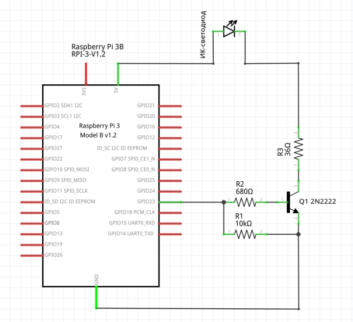
Mini-board schematic for IR LED
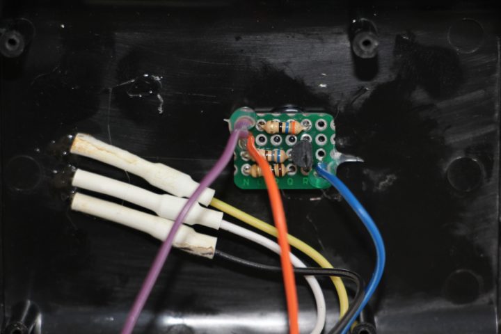
Mini-board for IR LED
The TSAL6200 infrared LED can continuously pass a current of 100mA. The maximum current you can draw from a single GPIO pin is 16mA and no more than 50mA from all pins combined. It is not possible to power the IR LED directly, as 16mA will be too low for its normal operation. Instead, we will assemble a small board to amplify the current.
Assemble the breadboard according to the provided schematic:
I cut a breadboard of this small size using a cutting disc on a Dremel mini drill from a larger breadboard. During soldering, pay special attention to the orientation of your transistor's 'emitter' and do not confuse its position when soldering it onto the board.
R1 is a pull-down resistor that ensures the IR LED remains off when the RPi's operating system is off or booting. In practice, the value of such a resistor is always 10kΩ. Although household electronics IR receivers receive signals in encoded form, and the chances of an RPi sending such a signal while powered off are extremely low, it's better to be safe and install this resistor.
R2 is the current limiting resistor for the transistor's 'base'. You need to calculate its value according to the 2N2222 transistor being used. We open its datasheet and see that its DC Current Gain ranges from 35 to 100 depending on current and voltage. I chose the absolute minimum and used a gain of 35 for the calculation. I need the 'base' control current to allow more than 100mA to flow from the 'collector' to the 'emitter'.
To calculate the 'base' current, we need to divide the required current by the DC current gain: 100mA / 35 = 2.9mA. I rounded up to 4mA for a margin, which will allow a current of up to 140mA to flow.
The voltage on the GPIO outputs is 3.3V. It is also necessary to account for the voltage drop from the transistor's 'base' to its 'emitter'. The Base-Emitter Saturation Voltage drop is 0.6V according to the datasheet. Therefore, to calculate the resistor needed to limit the GPIO current to 4 mA, we use Ohm's Law: V / I = R or (3.3V – 0.6V) / 4mA = 675 Ω. The nearest CF-25 resistor value is 680Ω.
We also need to calculate the power rating for resistor R2. The power formula is P = V * I or (3.3V – 0.6V) * 4mA = 0.011W. I chose 0.25W, as this was the smallest value among the resistors offered at the Chip and Dip store.
R3 limits the current passing through the IR LED. The LED will be powered from the GPIO 5V pin, which is directly connected to the 5V USB power. This means the maximum current you can draw from the 5V pin will be the maximum current of the power supply minus the current consumed by the RPi itself.
The forward voltage of the TSAL6200 is 1.35V and there will be a slight voltage drop (Collector-Emitter Saturation Voltage) from the 'collector' to the 'emitter' of our transistor, which is 0.3V (according to the datasheet). Then the value for R3 is calculated as follows: (5V – 1.35V – 0.3V) / 100mA = 33.5Ω. The nearest CF-25 resistor value was 36Ω, which corresponds to 93mA.
Finally, we need to calculate the power rating for R3. The power formula is P = V * I or (5V – 1.35V – 0.3V) * 93mA = 0.312W. This means we need a 1/2 W resistor for R3. But since this is the power at continuous IR LED operation, we can disregard this value. In practice, IR LEDs operate for fractions of a second with a 38kHz pulse, so you are applying voltage for a limited time, not continuously. Therefore, for R3, you can use a resistor with a lower power rating of 0.25W, not 0.5W.
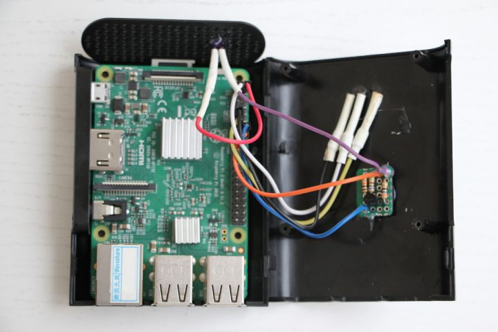
So, we solder the mini-board and then reinforce the wire entry points with hot glue. The mini-board itself is also glued to the RPi case lid using hot glue.
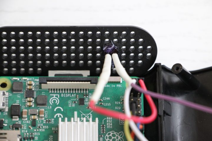
Connect the yellow wire to GPIO pin 23, the blue wire to GROUND, and solder the purple wire to the cathode of the IR LED, having first installed heat shrink tubing. The cathode on the LED is the shorter lead.
According to the datasheet, the soldering temperature should not exceed 260 degrees Celsius for more than 5 seconds. Solder the anode of the IR LED to a wire (having first installed heat shrink tubing), which in turn is connected to the 5V pin on the RPi. Next, place the heat shrink tubing over the solder joint, take a hot air gun, set the temperature to about 120 degrees, and shrink the tubing.
In the side grille of my RPi case, I drilled a 5mm hole, inserted the IR LED there, and secured it from the back with hot glue.
That's it, the 'hardware' assembly is complete, we can proceed to the software part.
2
Setting up LIRC to work with an IR LED
At this stage, you should already have the button codes from the remote controls used, and they should be written in the LIRC configuration. How to do this can be read in the instructions "Volume Control on Raspberry Pi with an IR Remote Control". This LIRC configuration is done for the joint use of the IR receiver and the IR LED on the RPi, with each using a separate lircd process, lirc-rx for the IR receiver and lirc-tx for the IR LED.
Turn on the RPi and access it via SSH.
Go to /boot/config.txt and set the GPIO output for the IR LED:
tinkster@almalinux:~#
1sudo nano /boot/config.txt
The file should have two lines, one for the IR receiver and one for the IR LED:
tinkster@almalinux:~#
1dtoverlay=gpio-ir,gpio_pin=172dtoverlay=gpio-ir-tx,gpio_pin=23
Create the file /etc/udev/rules.d/71-lirc.rules:
tinkster@almalinux:~#
1sudo nano /etc/udev/rules.d/71-lirc.rules
and insert the following lines into it:
tinkster@almalinux:~#
1ACTION=="add", SUBSYSTEM=="lirc", DRIVERS=="gpio_ir_recv", SYMLINK+="lirc-rx"2ACTION=="add", SUBSYSTEM=="lirc", DRIVERS=="gpio-ir-tx", SYMLINK+="lirc-tx"3ACTION=="add", SUBSYSTEM=="lirc", DRIVERS=="pwm-ir-tx", SYMLINK+="lirc-tx"
Next, open the file /etc/lirc/lirc_options.conf:
tinkster@almalinux:~#
1sudo nano /etc/lirc/lirc_options.conf
And change /div/lirc0 to /div/lirc-rx:
tinkster@almalinux:~#
1device = /dev/lirc-rx
Copy lirc_options.conf в lirc_tx_options.conf:
tinkster@almalinux:~#
1sudo cp /etc/lirc/lirc_options.conf /etc/lirc/lirc_tx_options.conf
and open the copied file:
tinkster@almalinux:~#
1sudo nano /etc/lirc/lirc_tx_options.conf
and change the following lines:
tinkster@almalinux:~#
1device = /dev/lirc-tx2output = /var/run/lirc/lircd-tx3pidfile = /var/run/lirc/lircd-tx.pid
Next, create the file /etc/systemd/system/lircd-tx.service:
tinkster@almalinux:~#
1sudo nano /etc/systemd/system/lircd-tx.service
and insert into it the content from the command output:
tinkster@almalinux:~#
1systemctl cat lircd
Edit it so that it looks like this:
tinkster@almalinux:~#
1[Unit]2Documentation=man:lircd(8)3Documentation=http://lirc.org/html/configure.html4Description=Second lircd, the transmitter5Wants=lircd-setup.service6After=network.target lircd-setup.service lircd.service78[Service]9Type=simple10ExecStart=/usr/sbin/lircd --nodaemon --options-file /etc/lirc/lirc_tx_options.conf11; User=lirc12; Group=lirc1314; Hardening opts, see systemd.exec(5). Doesn't add much unless15; not running as root.16;17; # Required for dropping privileges in --effective-user.18; CapabilityBoundingSet=CAP_SETEUID19; MemoryDenyWriteExecute=true20; NoNewPrivileges=true21; PrivateTmp=true22; ProtectHome=true23; ProtectSystem=full2425[Install]26WantedBy=multi-user.target
Next, create the file /etc/systemd/system/lircd-tx.socket:
tinkster@almalinux:~#
1sudo nano /etc/systemd/system/lircd-tx.socket
and insert into it the content from the command output:
tinkster@almalinux:~#
1systemctl cat lircd.socket
and edit it so that it looks like this:
tinkster@almalinux:~#
1[Socket]2ListenStream=/run/lirc/lircd-tx34[Install]5WantedBy=sockets.target6Also=lircd-tx.service
Restart the configuration manager systemd:
tinkster@almalinux:~#
1sudo systemctl daemon-reload
Start the process lirc-tx:
tinkster@almalinux:~#
1sudo systemctl start lircd-tx
Make lirc-tx load at system startup:
tinkster@almalinux:~#
1sudo systemctl enable lircd-tx
Next, create the file /usr/local/bin/irsend:
tinkster@almalinux:~#
1sudo nano /usr/local/bin/irsend
and insert the following lines into it:
tinkster@almalinux:~#
1#! /bin/sh2exec /usr/bin/irsend --device=/var/run/lirc/lircd-tx "$@"
Save the file and make it executable:
tinkster@almalinux:~#
1sudo chmod +x . /usr/local/bin/irsend
For reliability, let's restart the RPi:
tinkster@almalinux:~#
1sudo reboot
Next, access the RPi via SSH and try to send a signal from the IR LED to turn on, for example, the TV:
tinkster@almalinux:~#
1irsend --count=2 SEND_ONCE sony_tv KEY_POWER
The TV should turn on.
In my case, to turn on the TV, I need to send the signal 2 times continuously, which is controlled by the parameter -count=2 In your case, this may not be necessary.
To make sure that your IR LED is actually emitting infrared radiation, you can do the following. Open the camera on your smartphone and point it at the LED, at the same time run the command from the terminal mentioned above, and you should see a brief glow of the LED on the smartphone screen. If this does not happen, you need to check the LIRC logs and also verify the connection diagram.
3
Integration of an IR LED with Alexa voice control
Integration of an IR LED with Alexa voice control
Integration of an IR LED with Alexa voice control
We will configure this functionality through the chain: Alexa – service IFTTT – web server Apache with PHP on RPi – execution of a terminal command shell_exec.
You also need to have a fixed IP address for your router and forwarded ports 80 or 443 to the local IP address of your RPi.
Install Apache and PHP:
In the folder
tinkster@almalinux:~#
1sudo apt install apache2 && sudo apt install php libapache2-mod-php
of your web server, create a file /var/www/html/ and insert the following code into it:home_control.php
tinkster@almalinux:~#
1<?php2if (isset($_POST['code'])) $code = $_POST['code']; else $code = "";3$code_sony_tv = "WVO4RZRi";4$cmd_sony_tv = "irsend SEND_ONCE sony_tv KEY_POWER";5if ($code == $code_sony_tv) shell_exec($cmd_sony_tv);6?>
This code is demonstrational and does not account for the security of your activation codes on the server. For greater security, you can store the hash-values of your codes in a database and take them from there for comparison.
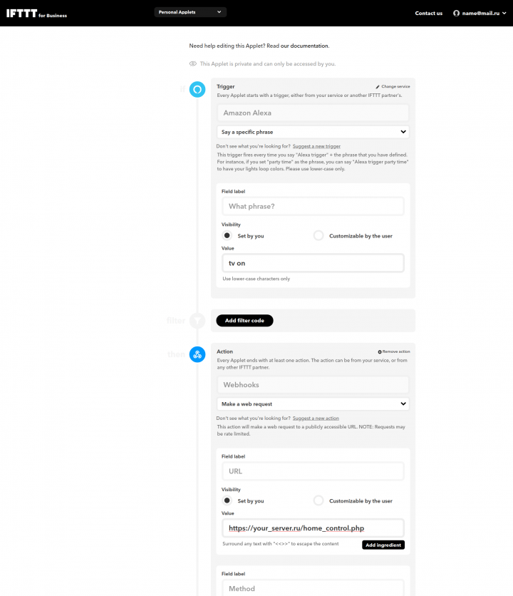
Next, we register on the IFTTT service and create a personal applet (Personal Applet). In the Trigger field, we select Amazon Alexa, in the field below we select Say a specific phrase. In the Value field of the block What phrase? we enter tv on. The activation phrase on Alexa will then sound like this: "Alexa, trigger tv on".
Then in the Actions block, we select Webhooks and in the field below we select Make a web request. In the Value field of the URL block, we enter the URL address (instead of a domain name, you can use the router’s IP address) to your PHP script on the RPi.
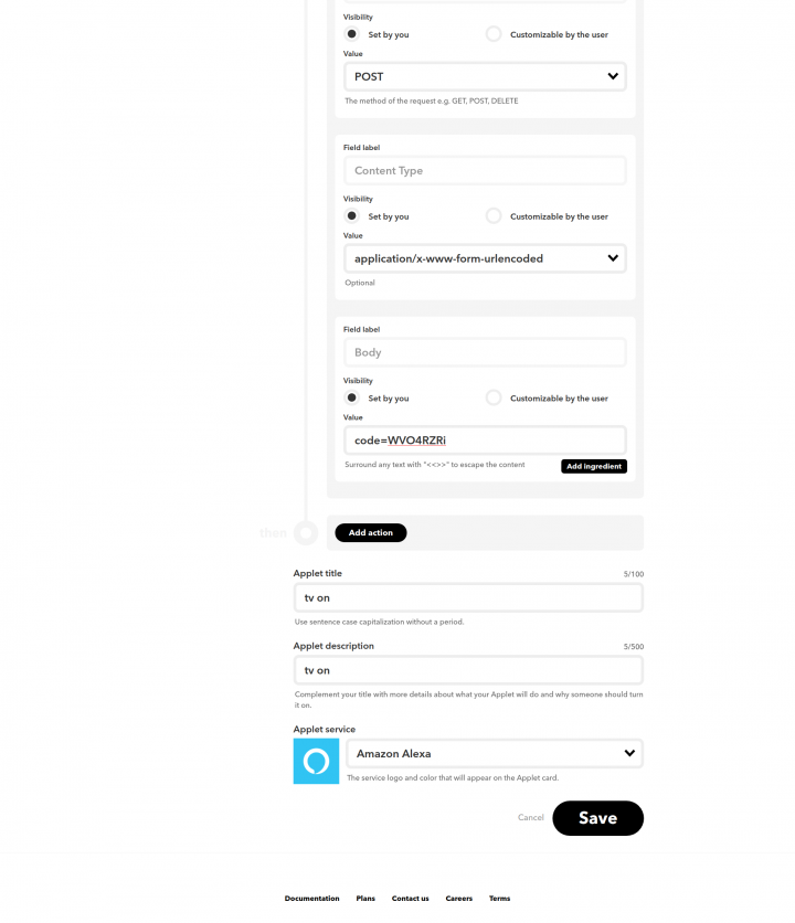
Then in the Method block in the Value drop-down menu, we select POST, and in the next Content Type block, we select application/x-www-form-urlencoded.
In the last Body block in the Value field, we specify the activation code that will be passed to the PHP script. In Applet title and Applet description, you can also specify – tv on.
We save this applet and activate it.
After this, we check the functionality through the voice assistant with Alexa. If everything is done correctly, after the activation phrase Alexa will turn on your TV! An analogous applet can be made for turning off the TV and assigning the phrase for turning off — tv off.
The only minus of such control is that the remote button code for turning on/off is the same and the system does not know the state of your TV at the current moment. Therefore, if the TV is turned off and you ask Alexa: "Alexa, trigger tv off", it will conversely turn on. But I think that the convenience of controlling your devices in the house with the help of voice will outweigh this minus.
Discussion (0)
No comments yet. Be the first!
Maker
Anton Shagaev
Tomsk, RU
Anton is the Founding Engineer at Tinkster. He translates industrial reliability into software architecture, ensuring the platform's core is built to last. Anton studied oil and gas engineering in the United States and also holds two honors degrees from Tomsk Polytechnic University.
Related Projects
AI Project Assistant
Tinkster Neural Core
Hi! I am the AI assistant for this project. Ask me any questions about the assembly, code, or components.