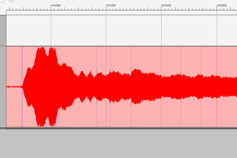
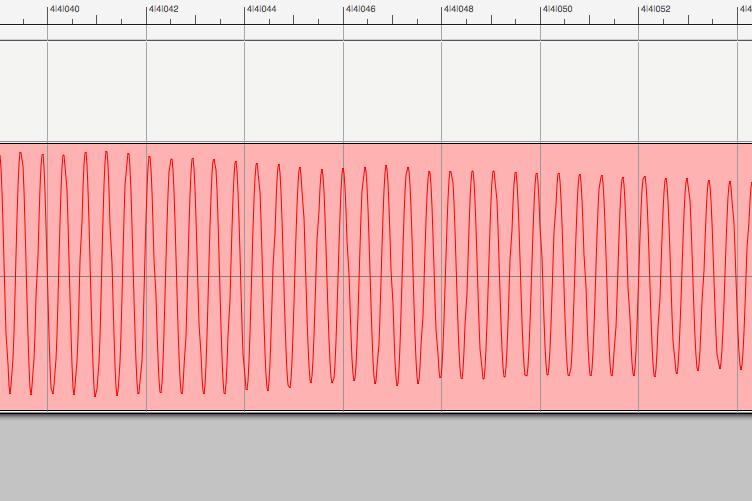
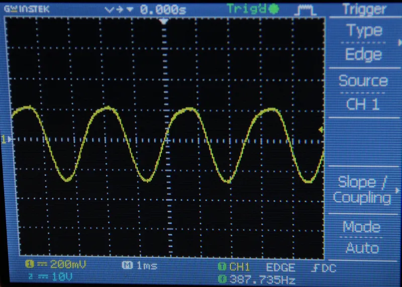
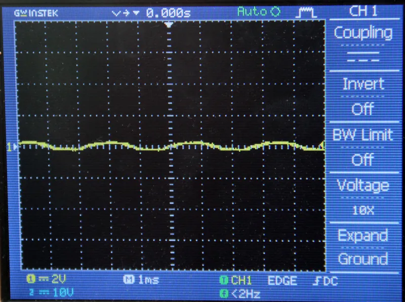
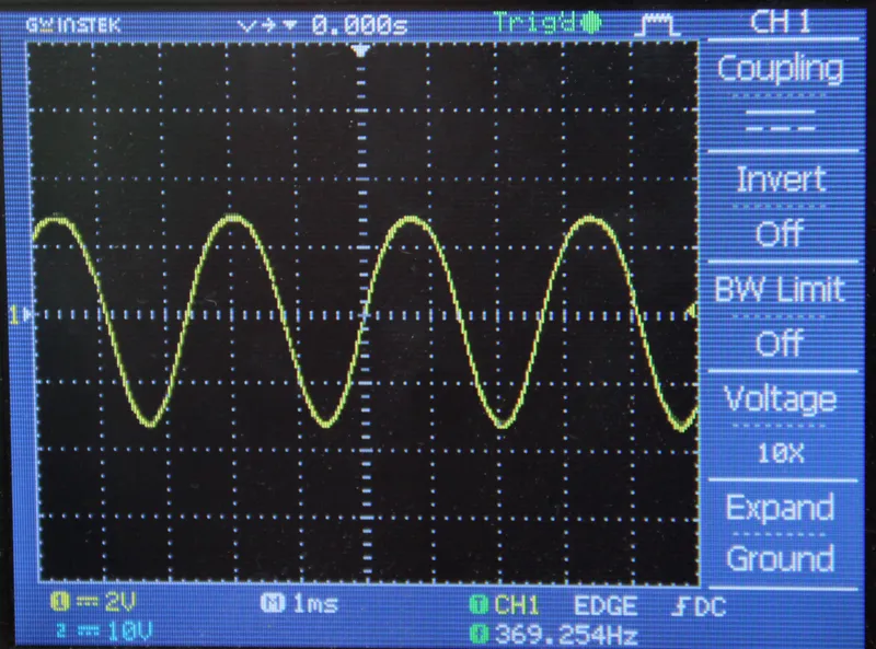
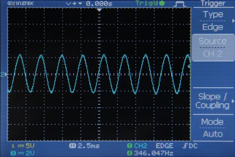
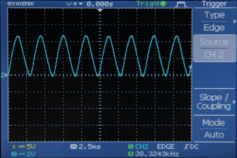
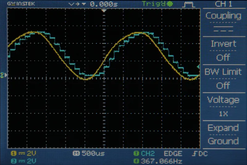
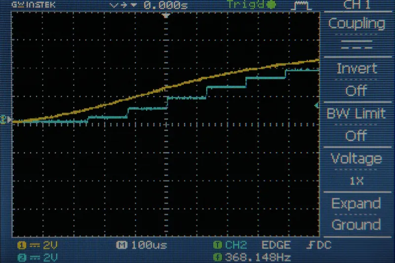
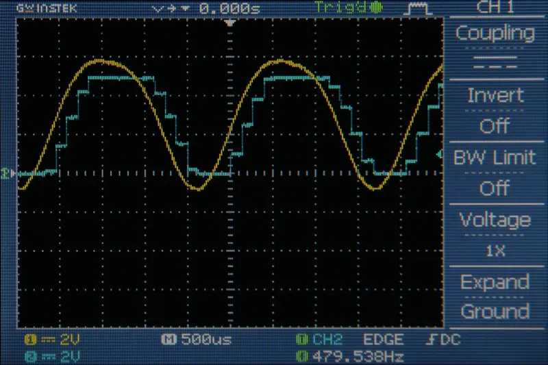
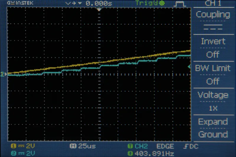
A clipping indicator LED is useful so that you know if you need to turn the gain down on your amplifier. If your signal is clipping as it comes into the Arduino, you are losing information about the signal. Figs 2 and 3 show the incoming signal (yellow) and the data stored in the Arduino (blue) for both 8kHz and 38.5kHz sampling rates. Notice how the Arduino completely misses the behavior of the peaks and valleys due to clipping.
To set up the clipping counter I created a few new variables. "clipping" has a state of 1 when the Arduino detects clipping (the incoming signal is measured to be 0 or 5V) and a state of 0 when the Arduino does not detect clipping. In the code below (for 8kHz sampling rate) I also set up a variable called clippingCounter. The purpose of this variable is to keep the indicator LED on for a moment after the clipping was detected so that it is visible to the human eye. In the 38.5kHz code (at the bottom of this step) I used a delay(100) to achieve the same effect.
//Simple Audio In with clipping indicator
//by Amanda Ghassaei
//https://www.instructables.com/id/Arduino-Audio-Input/
//Sept 2012
/*
* This program is free software; you can redistribute it and/or modify
* it under the terms of the GNU General Public License as published by
* the Free Software Foundation; either version 3 of the License, or
* (at your option) any later version.
*
*/
int incomingAudio;
boolean clipping = 0;//zero = not clipping, one = currently clipping
int clippingCounter = 5000;
void setup(){
}
void loop(){
incomingAudio = analogRead(A0);//read input from A0
//do stuff with the variable "incomingAudio"
if (incomingAudio == 0 || incomingAudio == 1023){//if clipping
digitalWrite(13,HIGH);//set pin 13 high
clipping = 1;//currently clipping
clippingCounter = 5000;//reset clippingCounter
}
if (clipping){
if (clippingCounter>0){
clippingCounter--;//decrement clipping counter
}
else{//if clippingCounter has counted all the way down
clipping = 0;//no longer clipping
digitalWrite(13,LOW);//turn of clipping indicator
}
}
}
and below is the code for 38.5kHz with interrupts:
//Audio in with 38.5kHz sampling rate, interrupts, and clipping indicator
//by Amanda Ghassaei
//https://www.instructables.com/id/Arduino-Audio-Input/
//Sept 2012
/*
* This program is free software; you can redistribute it and/or modify
* it under the terms of the GNU General Public License as published by
* the Free Software Foundation; either version 3 of the License, or
* (at your option) any later version.
*
*/
//variable to store incoming audio sample
byte incomingAudio;
//clipping indicator variables
boolean clipping = 0;
void setup(){
pinMode(13,OUTPUT);//led indicator pin
cli();//disable interrupts
//set up continuous sampling of analog pin 0
//clear ADCSRA and ADCSRB registers
ADCSRA = 0;
ADCSRB = 0;
ADMUX |= (1 << REFS0); //set reference voltage
ADMUX |= (1 << ADLAR); //left align the ADC value- so we can read highest 8 bits from ADCH register only
ADCSRA |= (1 << ADPS2) | (1 << ADPS0); //set ADC clock with 32 prescaler- 16mHz/32=500kHz
ADCSRA |= (1 << ADATE); //enabble auto trigger
ADCSRA |= (1 << ADIE); //enable interrupts when measurement complete
ADCSRA |= (1 << ADEN); //enable ADC
ADCSRA |= (1 << ADSC); //start ADC measurements
sei();//enable interrupts
//if you want to add other things to setup(), do it here
}
ISR(ADC_vect) {//when new ADC value ready
incomingAudio = ADCH;//store 8 bit value from analog pin 0
if (incomingAudio == 0 || incomingAudio == 255){//if clipping
digitalWrite(13,HIGH);//set pin 13 high
clipping = 1;//currently clipping
}
}
void loop(){
if (clipping){//if currently clipping
clipping = 0;//
digitalWrite(13,LOW);//turn off clipping led indicator (pin 13)
}
delay(100);
}