Timer setup code is done inside the setup(){} function in an Arduino sketch.
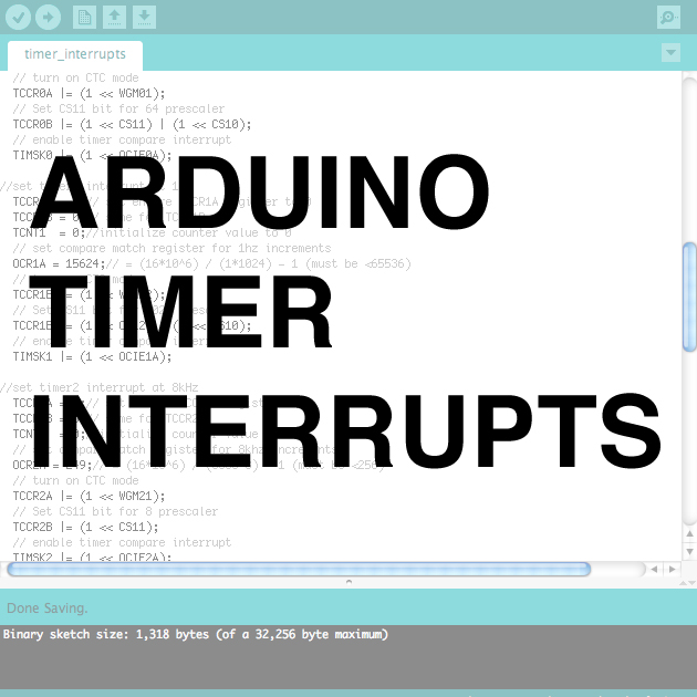
The code involved for setting up timer interrupts is a little daunting to look at, but it's actually not that hard. I pretty much just copy the same main chunk of code and change the prescaler and compare match register to set the correct interrupt frequency.
The main structure of the interrupt setup looks like this:
//https://www.instructables.com/id/Arduino-Timer-Interrupts/
void setup(){
cli();//stop interrupts
//set timer0 interrupt at 2kHz
TCCR0A = 0;// set entire TCCR0A register to 0
TCCR0B = 0;// same for TCCR0B
TCNT0 = 0;//initialize counter value to 0
// set compare match register for 2khz increments
OCR0A = 124;// = (16*10^6) / (2000*64) - 1 (must be <256)
// turn on CTC mode
TCCR0A |= (1 << WGM01);
// Set CS01 and CS00 bits for 64 prescaler
TCCR0B |= (1 << CS01) | (1 << CS00);
// enable timer compare interrupt
TIMSK0 |= (1 << OCIE0A);
//set timer1 interrupt at 1Hz
TCCR1A = 0;// set entire TCCR1A register to 0
TCCR1B = 0;// same for TCCR1B
TCNT1 = 0;//initialize counter value to 0
// set compare match register for 1hz increments
OCR1A = 15624;// = (16*10^6) / (1*1024) - 1 (must be <65536)
// turn on CTC mode
TCCR1B |= (1 << WGM12);
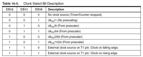
// Set CS10 and CS12 bits for 1024 prescaler
TCCR1B |= (1 << CS12) | (1 << CS10);
// enable timer compare interrupt
TIMSK1 |= (1 << OCIE1A);
//set timer2 interrupt at 8kHz
TCCR2A = 0;// set entire TCCR2A register to 0
TCCR2B = 0;// same for TCCR2B
TCNT2 = 0;//initialize counter value to 0
// set compare match register for 8khz increments
OCR2A = 249;// = (16*10^6) / (8000*8) - 1 (must be <256)
// turn on CTC mode
TCCR2A |= (1 << WGM21);
// Set CS21 bit for 8 prescaler
TCCR2B |= (1 << CS21);
// enable timer compare interrupt
TIMSK2 |= (1 << OCIE2A);
sei();//allow interrupts
}//end setup Notice how the value of OCR#A (the compare match value) changes for each of these timer setups. As explained in the last step, this was calculated according to the following equation:
compare match register = [ 16,000,000Hz/ (prescaler * desired interrupt frequency) ] - 1
remember that when you use timers 0 and 2 this number must be less than 256, and less than 65536 for timer1
Also notice how the setups between the three timers differ slightly in the line which turns on CTC mode:
TCCR0A |= (1 << WGM01);//for timer0
TCCR1B |= (1 << WGM12);//for timer1
TCCR2A |= (1 << WGM21);//for timer2
This follows directly from the datasheet of the ATMEL 328/168.
Finally, notice how the setup for the prescalers follows the tables in the last step (the table for timer 0 is repeated above),
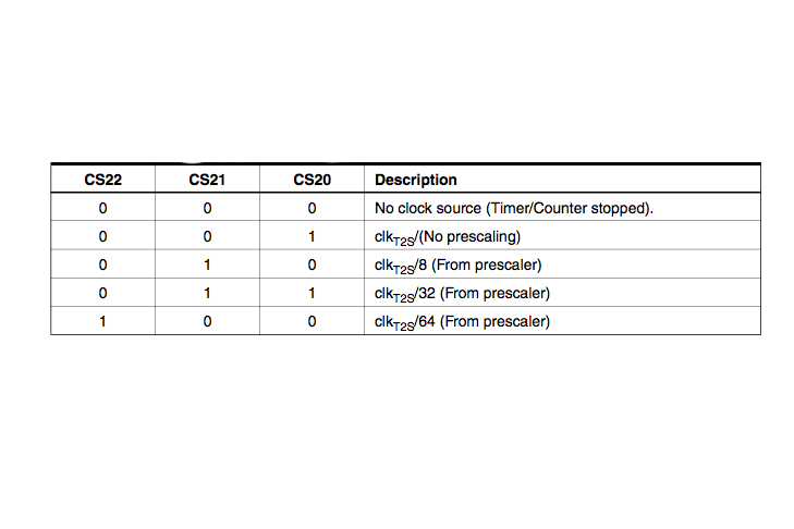
TCCR2B |= (1 << CS22); // Set CS#2 bit for 64 prescaler for timer 2
TCCR1B |= (1 << CS11); // Set CS#1 bit for 8 prescaler for timer 1
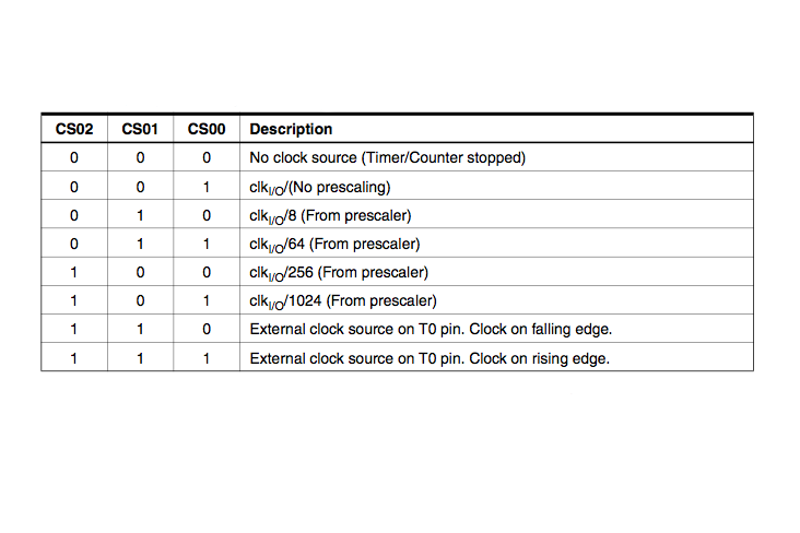
TCCR0B |= (1 << CS02) | (1 << CS00); // Set CS#2 and CS#0 bits for 1024 prescaler for timer 0
Notice in the last step that there are different prescaling options for the different timers. For example, timer2 does not have the option of 1024 prescaler.
The commands you want to execute during these timer interrupts are located in the Arduino sketch encapsulated in the following:
ISR(TIMER0_COMPA_vect){ //change the 0 to 1 for timer1 and 2 for timer2
//interrupt commands here
}
This bit of code should be located outside the setup() and loop() functions. Also, try to keep the interrupt routine as short as possible, especially if you are interrupting at a high frequency. It may even be worth addressing the ports/pins of the ATMEL chip directly instead of using the digitalWrite() and digitalRead() functions. You can find more info about that here. Example- the following sketch sets up and executes 3 timer interrupts:
//timer interrupts
//by Amanda Ghassaei
//June 2012
//https://www.instructables.com/id/Arduino-Timer-Interrupts/
/*
* This program is free software; you can redistribute it and/or modify
* it under the terms of the GNU General Public License as published by
* the Free Software Foundation; either version 3 of the License, or
* (at your option) any later version.
*
*/
//timer setup for timer0, timer1, and timer2.
//For arduino uno or any board with ATMEL 328/168.. diecimila, duemilanove, lilypad, nano, mini...
//this code will enable all three arduino timer interrupts.
//timer0 will interrupt at 2kHz
//timer1 will interrupt at 1Hz
//timer2 will interrupt at 8kHz
//storage variables
boolean toggle0 = 0;
boolean toggle1 = 0;
boolean toggle2 = 0;
void setup(){
//set pins as outputs
pinMode(8, OUTPUT);
pinMode(9, OUTPUT);
pinMode(13, OUTPUT);
cli();//stop interrupts
//set timer0 interrupt at 2kHz
TCCR0A = 0;// set entire TCCR2A register to 0
TCCR0B = 0;// same for TCCR2B
TCNT0 = 0;//initialize counter value to 0
// set compare match register for 2khz increments
OCR0A = 124;// = (16*10^6) / (2000*64) - 1 (must be <256)
// turn on CTC mode
TCCR0A |= (1 << WGM01);
// Set CS01 and CS00 bits for 64 prescaler
TCCR0B |= (1 << CS01) | (1 << CS00);
// enable timer compare interrupt
TIMSK0 |= (1 << OCIE0A);
//set timer1 interrupt at 1Hz
TCCR1A = 0;// set entire TCCR1A register to 0
TCCR1B = 0;// same for TCCR1B
TCNT1 = 0;//initialize counter value to 0
// set compare match register for 1hz increments
OCR1A = 15624;// = (16*10^6) / (1*1024) - 1 (must be <65536)
// turn on CTC mode
TCCR1B |= (1 << WGM12);
// Set CS12 and CS10 bits for 1024 prescaler
TCCR1B |= (1 << CS12) | (1 << CS10);
// enable timer compare interrupt
TIMSK1 |= (1 << OCIE1A);
//set timer2 interrupt at 8kHz
TCCR2A = 0;// set entire TCCR2A register to 0
TCCR2B = 0;// same for TCCR2B
TCNT2 = 0;//initialize counter value to 0
// set compare match register for 8khz increments
OCR2A = 249;// = (16*10^6) / (8000*8) - 1 (must be <256)
// turn on CTC mode
TCCR2A |= (1 << WGM21);
// Set CS21 bit for 8 prescaler
TCCR2B |= (1 << CS21);
// enable timer compare interrupt
TIMSK2 |= (1 << OCIE2A);
sei();//allow interrupts
}//end setup
ISR(TIMER0_COMPA_vect){//timer0 interrupt 2kHz toggles pin 8
//generates pulse wave of frequency 2kHz/2 = 1kHz (takes two cycles for full wave- toggle high then toggle low)
if (toggle0){
digitalWrite(8,HIGH);
toggle0 = 0;
}
else{
digitalWrite(8,LOW);
toggle0 = 1;
}
}
ISR(TIMER1_COMPA_vect){//timer1 interrupt 1Hz toggles pin 13 (LED)
//generates pulse wave of frequency 1Hz/2 = 0.5kHz (takes two cycles for full wave- toggle high then toggle low)
if (toggle1){
digitalWrite(13,HIGH);
toggle1 = 0;
}
else{
digitalWrite(13,LOW);
toggle1 = 1;
}
}
ISR(TIMER2_COMPA_vect){//timer1 interrupt 8kHz toggles pin 9
//generates pulse wave of frequency 8kHz/2 = 4kHz (takes two cycles for full wave- toggle high then toggle low)
if (toggle2){
digitalWrite(9,HIGH);
toggle2 = 0;
}
else{
digitalWrite(9,LOW);
toggle2 = 1;
}
}
void loop(){
//do other things here
}
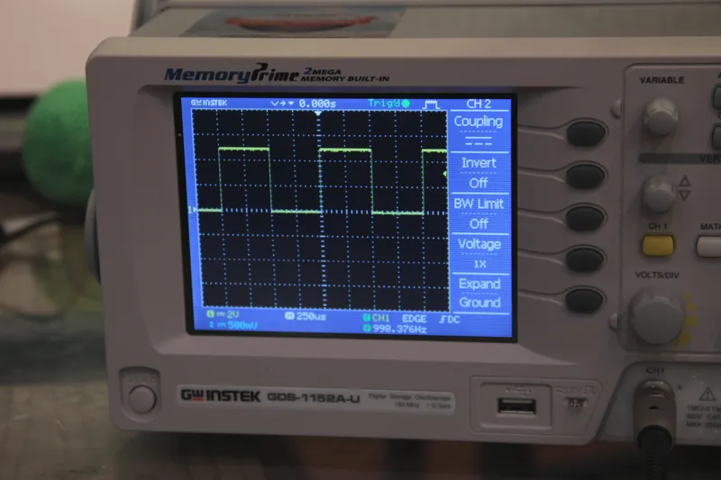
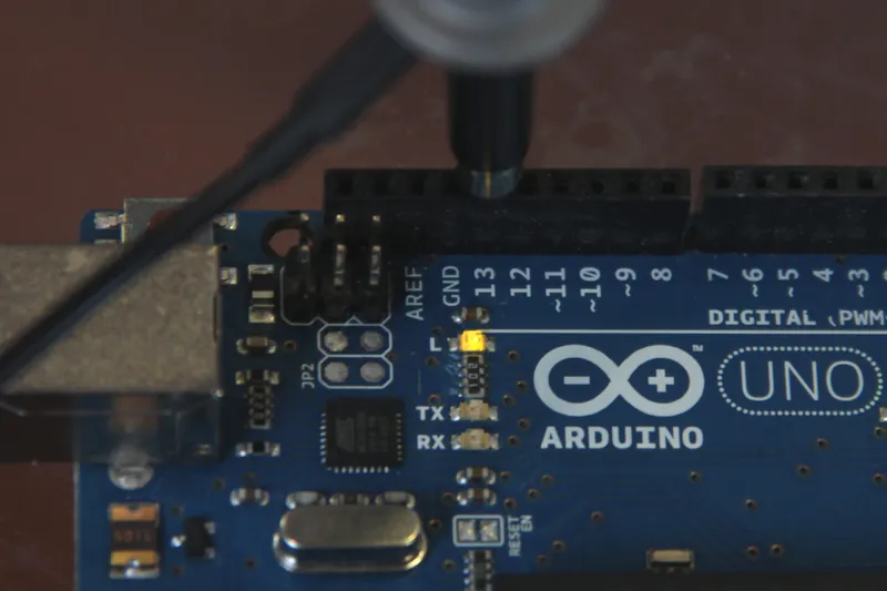
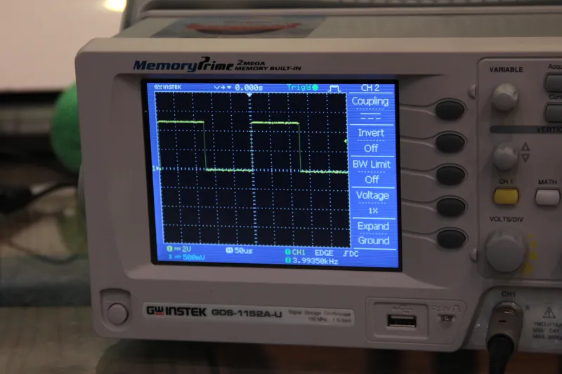
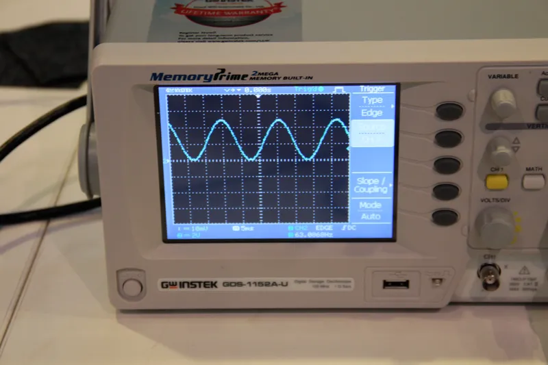
The images above show the outputs from these timer interrupts. Fig 1 shows a square wave oscillating between 0 and 5V at 1kHz (timer0 interrupt), fig 2 shows the LED attached to pin 13 turning on for one second then turning off for one second (timer1 interrupt), fig 3 shows a pulse wave oscillating between 0 and 5V at a frequency of 4khz (timer2 interrupt).