The MicroSlice uses Grbl v0.8 for motion control. Grbl converts G-Code into commands that the EasyDriver stepper motor controllers understand. We need another program to send the G-Code to Grbl, for this I'll be using Zapmaker's Grbl Controller v3.0. Before you can begin you will need the Arduino IDE, available from the Arduino website. Make sure your Laser Diode is not connected to the power lines while you are configuring your MicroSlice. The Laser will power on & off during the setup & configuration process if it is connected. Only connect the Laser Diode when you are ready to cut or engrave.
For those of you who have a Raspberry Pi, as I do, you'll be pleased to know that you can control the MicroSlice using your Pi! Zapmaker has a step-by-step guide to install Grbl Controller on a Raspberry Pi. We'll need to generate some G-Code. The best way to do this is to use Inkscape combined with a laser engraver plug-in. An Open Source vector graphics editor, with capabilities similar to Illustrator, CorelDraw, or Xara X, using the W3C standard Scalable Vector Graphics (SVG) file format. I've been using the same plug-in Groover made for his engraver, he has done a short video detailing its use. Before we can use our new G-Code we'll need to configure Grbl to use the stepper motors and end-stops.
You can use either the Arduino IDE Serial Terminal (CTRL + Shift + M) to send commands to Grbl. Sending $$ to Grbl displays the configuration settings (yours might look differently);
$0=755.906 (x, step/mm)
$1=755.906 (y, step/mm)
$2=755.906 (z, step/mm)
$3=30 (step pulse, usec)
$4=500.000 (default feed, mm/min)
$5=500.000 (default seek, mm/min)
$6=28 (step port invert mask, int:00011100)
$7=25 (step idle delay, msec)
$8=50.000 (acceleration, mm/sec^2)
$9=0.050 (junction deviation, mm)
$10=0.100 (arc, mm/segment)
$11=25 (n-arc correction, int)
$12=3 (n-decimals, int)
$13=0 (report inches, bool)
$14=1 (auto start, bool)
$15=0 (invert step enable, bool)
$16=0 (hard limits, bool)
$17=0 (homing cycle, bool)
$18=0 (homing dir invert mask, int:00000000)
$19=25.000 (homing feed, mm/min)
$20=250.000 (homing seek, mm/min)
$21=100 (homing debounce, msec)
$22=1.000 (homing pull-off, mm)
The settings we are interested in are $0 & $1. These two setting configure the A & Y Axis. We'll need to calculate the number of steps to move the cutting head 1mm in either direction.
We calculate it thus;
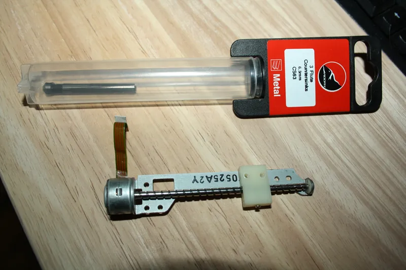
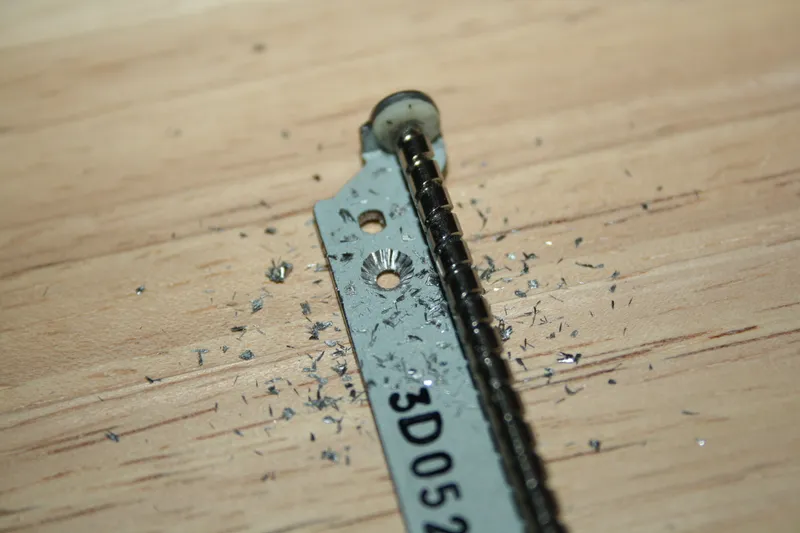
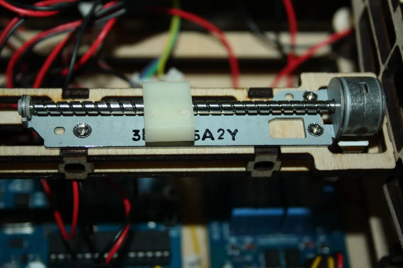
Number of Steps = Number of steps per rotation x Microsteps / Thread Pitch
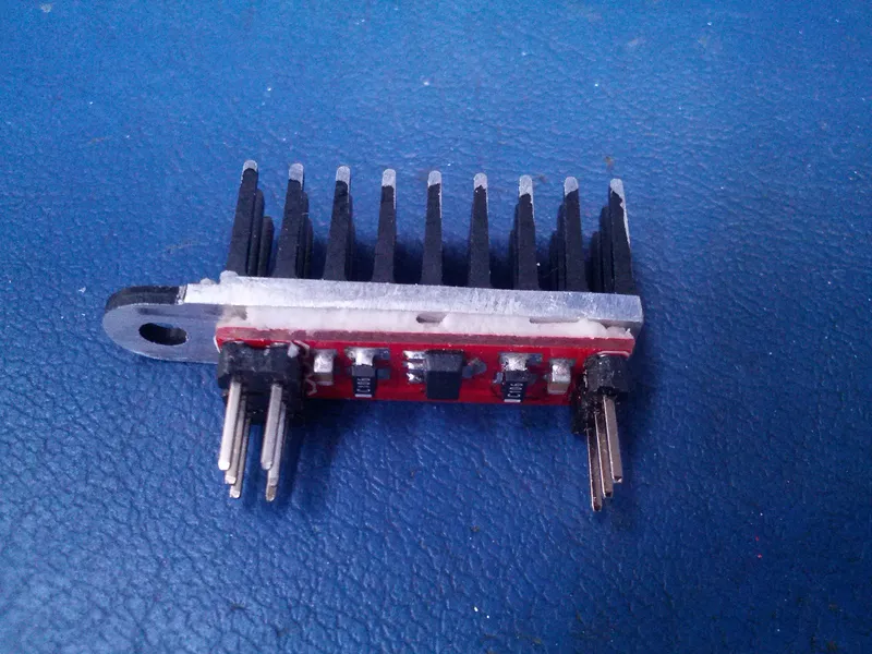
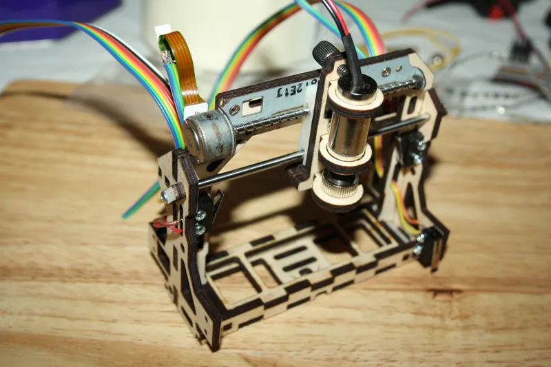
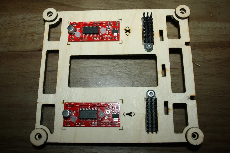
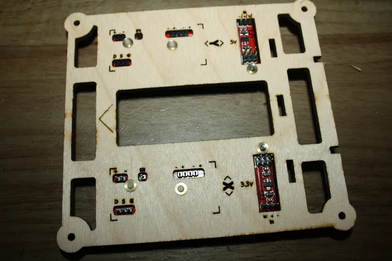
20 Steps-a-Turn (18 Degrees a step) x 8 Microsteps (MS1 & MS2 Connected to +5v on the EasyDrivers) / 3mm Thread pitch (3mm of travel per rotation).
(20 x 8) / 3 = 53.333333333
So type $0=53.333 and $1=53.333 into the terminal to setup the axis. You will need to do a soft reset for the changes to take effect ($X).
Or you can use Zapmaker's Grbl Controller to adjust Grbl. You can access the Grbl Settings via the advanced tab. You'll still need a soft reset after clicking apply.
You should also set;
$4=200 This sets the default speed the cutting head moves at while working.
$5=200 This sets the default speed the cutting head moves at while moving between jobs.
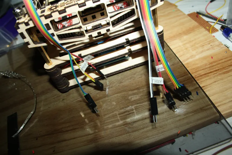
$16=1 This enables the end-stops.
$17=1 This enables homing ($H), mine locks up when I try to run the homing cycle. To enable this function you will need to edit the source code for Grbl and recompile the .hex file. Instructions showing how to do this are at the bottom of this Step.
$18=69 This will make the cutter zero in the lower left of the cutting table when the $H homing command is executed. For an in-depth explanation of this function see the Grbl Wiki. $19=200
$20=200
$22=2.000 This sets the distance the Axis moves away form the end-stops after the homing cycle.
There are in-depth explanations for each of Grbl's settings on the Grbl Wiki. Check your configuration is correct by typing $$ into the terminal. You should see something like this;
$0=53.333 (x, step/mm)
$1=53.333 (y, step/mm)
$2=53.330 (z, step/mm)
$3=10 (step pulse, usec)
$4=200.000 (default feed, mm/min)
$5=200.000 (default seek, mm/min)
$6=28 (step port invert mask, int:00011100)
$7=50 (step idle delay, msec)
$8=100.000 (acceleration, mm/sec^2)
$9=0.050 (junction deviation, mm)
$10=0.100 (arc, mm/segment)
$11=25 (n-arc correction, int)
$12=3 (n-decimals, int)
$13=0 (report inches, bool)
$14=1 (auto start, bool)
$15=0 (invert step enable, bool)
$16=1 (hard limits, bool)
$17=1 (homing cycle, bool)
$18=69 (homing dir invert mask, int:00000000)
$19=200.000 (homing feed, mm/min)
$20=200.000 (homing seek, mm/min)
$21=100 (homing debounce, msec)
$22=2.000 (homing pull-off, mm)
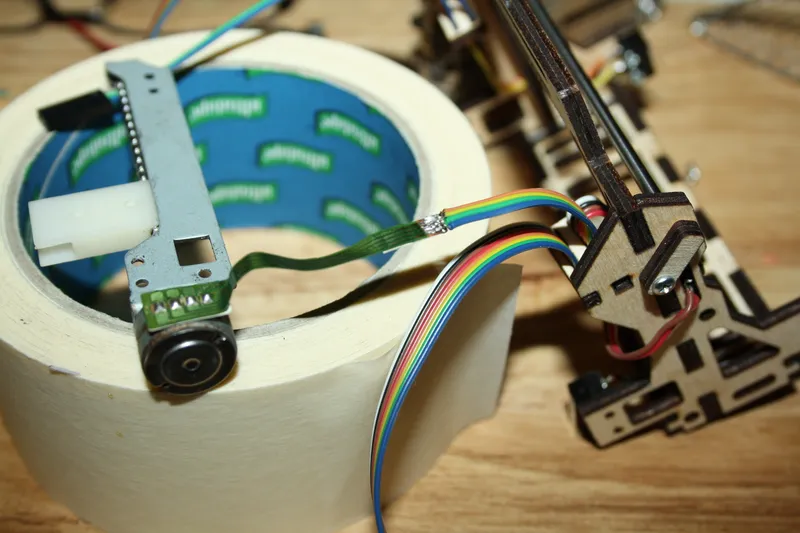
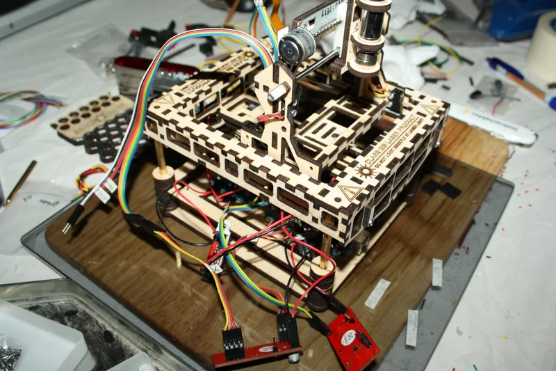
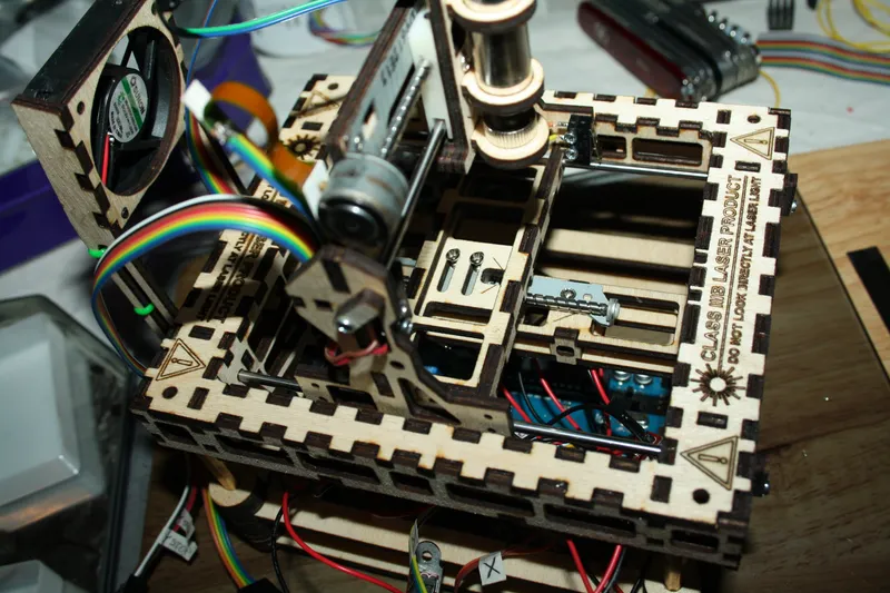
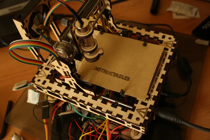
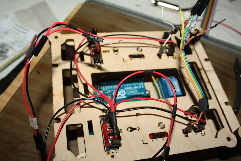
The final step is to focus the laser. I loaded a small test sample, in this case it was an X, and let the sequence run.
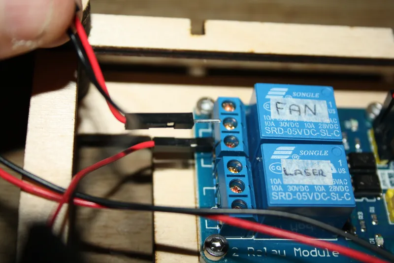
You can power the Laser Diode On & Off using the tick box labelled Spindle On on Zapmaker's Grbl Controller.
The first time there was nothing there, but are a few turns of the lens I managed to get a mark on some paper. After that all it needed was a bit of fine tuning and the laser was correctly focused on the cutting table.
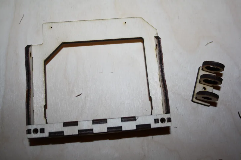
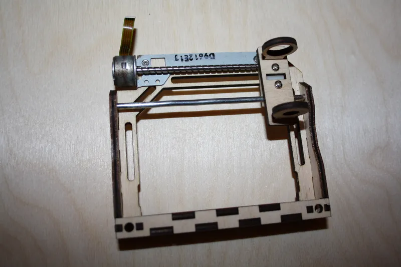
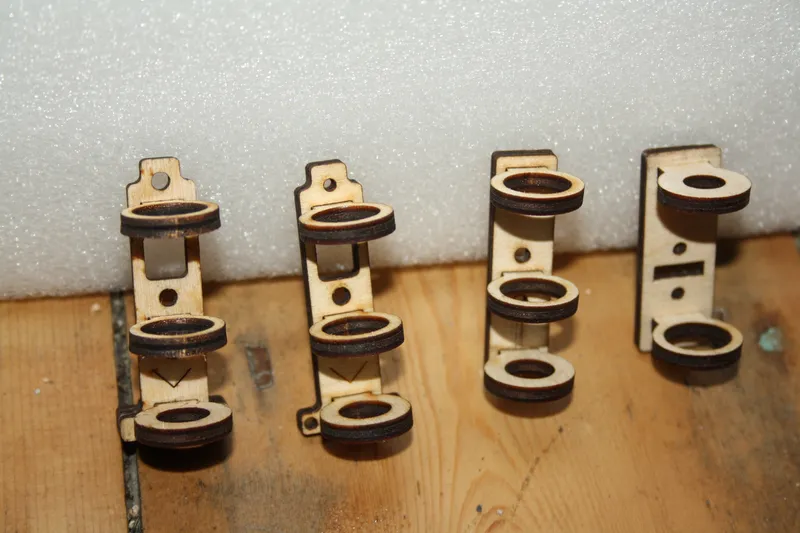
I made some 3mm spacers to go under the lase module to lift it up for when I wanted to engrave some 3mm plywood. Doing so meant I didn't have to refocus the lens each time I wanted to swap materials.
Editing The Source Code.
During testing I found that Grbl would hang on the $H (homing) command. I suspected this was a problem with the Z Axis as the MicroSlice does not have one.
To fix the probem we must remove the Z Axis options from the Homing Cycle. The commands are contained within the config.h file in the source code.
1 | Download the source code from Grbl (link). 2 | Unpack the archive.
3 | Open config.h in your favourite text editor. 4 | Locate the following code
#define HOMING_SEARCH_CYCLE_0 (1< #define HOMING_SEARCH_CYCLE_1 ((1<
5 | Replace the code with
// #define HOMING_SEARCH_CYCLE_0 (1<
#define HOMING_SEARCH_CYCLE_0 ((1<
6 | Locate the following code
#define HOMING_LOCATE_CYCLE ((1<
7 | Replace the code with
#define HOMING_LOCATE_CYCLE ((1<
6 | Save
7 | Recompile the grbl.hex file. I used my Raspberry Pi to recompile the hex. In case things go wrong I have included the modified hex file for you below. You'll need to flash your Arduino with the new hex.|||/BOLD|||
If everything has worked, and all the settings are configured correctly you should be able to run the homing cycle ($H) and see the MicroSlice zero itself and then you should be ready to go create!