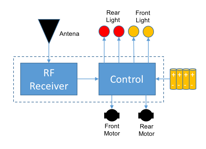
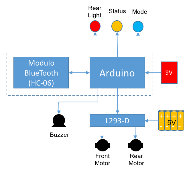
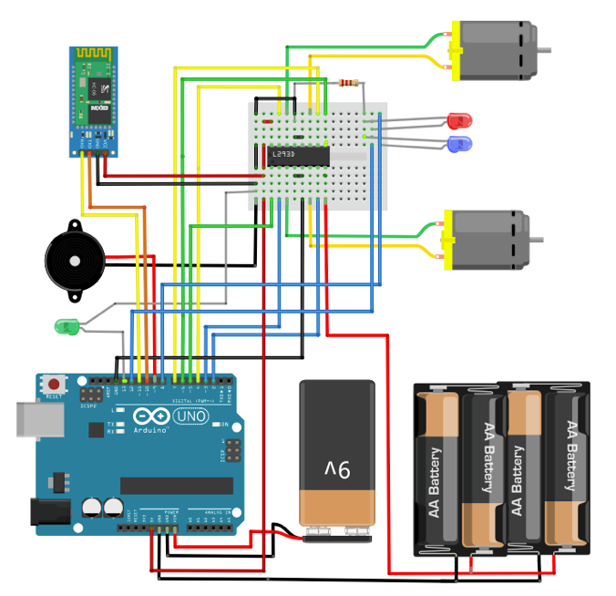
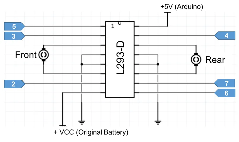
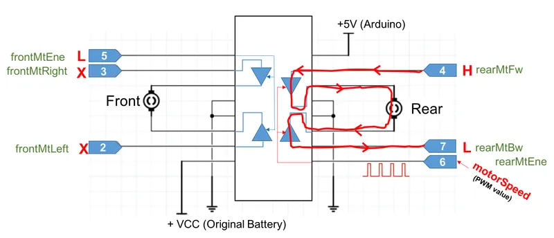
The front and rear motors are connected to H-bridge as shown in the above diagram, and each of the Arduino pins, which should be defined as an OUTPUT during setup, will have a variable assigned:
// Motor Drives
const int rearMtFw = 4; // Rear Motor - FW
const int rearMtBw = 7; // Rear Motor - BW
const int rearMtEne = 6; // Rear Motor - enable
const int frontMtLeft = 2; // Front Motor - turn Left
const int frontMtRight = 3; // Front Motor - turn right
const int frontMtEne = 5; // Front Motor enable
For example, if we want to move the car forward, the moveForward () function will put the pin 4 in HIGH and pin 7 in LOW, this will cause the current to flow "clockwise" as shown in the second above diagram.
Pin 6 is the "enable" what means that only when it is in "HIGH", the bridge will allow current flowing to motors. Because this pin is a PWM type, the speed on which the motor will turn, depend on the value of "MotorSpeed" variable, at pin 6 (value range from 0 to 255).
The function should also ensure that the front engine "rotate freely" and for that, the pin 5 which is the pin "enable", should be LOW (the status of pins 2 and 3 do not matter, since the enable is LOW). The LED "ledRed" that emulates a "reverse gear light" should always be off when the car moves forward:
void moveForward() // rear motor FW
{
analogWrite(rearMtEne, motorSpeed);
digitalWrite(rearMtFw, HIGH);
digitalWrite(rearMtBw, LOW);
digitalWrite(frontMtEne, LOW);
digitalWrite(ledRed, LOW);
delay(5);
}By analogy, it is obvious that to make the car "move back", the motor must rotate in the opposite direction. For this, the pin 4 must be LOW and HIGH pin 7. Note that in this case of the " reverse gear light" should be on. The function in this case will be:
void moveBackward() // rear motor BW
{
analogWrite(rearMtEne, motorSpeed);
digitalWrite(rearMtFw, LOW);
digitalWrite(rearMtBw, HIGH);
digitalWrite(frontMtEne, LOW);
digitalWrite(ledRed, HIGH);
delay(5);
}
The same reasoning can be used for the front engine, only that in this case there is no speed control. Putting the pin 2 (enable) HIGH enables the engine to "try to turn" to one side or the other depending on the status of pins 2 and 3:
void moveLeft() // front motor left
{
digitalWrite(frontMtEne, HIGH);
digitalWrite(frontMtLeft, HIGH);
digitalWrite(frontMtRight, LOW);
digitalWrite(ledRed, LOW);
delay(10);
}
//******************************************************************************//
void moveRight() // front motor right
{
digitalWrite(frontMtEne, HIGH);
digitalWrite(frontMtLeft, LOW);
digitalWrite(frontMtRight, HIGH);
digitalWrite(ledRed, LOW);
delay(10);
}
To stop the car, just put all the bridge's outputs for the rear motor in LOW, what will "catch" the motor shaft . For the front motor, just put the enable pin in LOW):
void stopRobot ()
{
digitalWrite(ledBlue, LOW);
digitalWrite(ledRed, LOW);
state = 0;
moveStop(); //turn off both motors
}
In the link below, you can find the complete code for the Arduino: