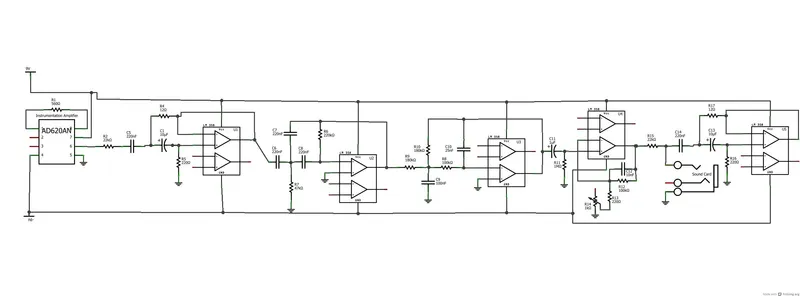
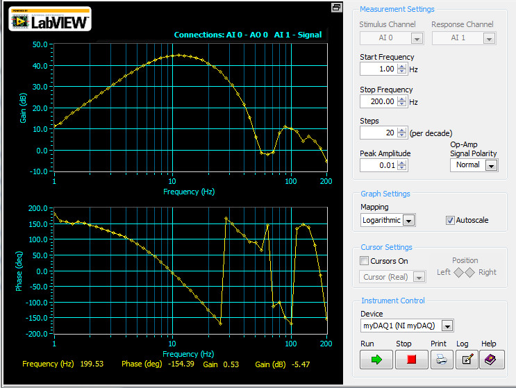
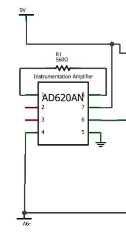
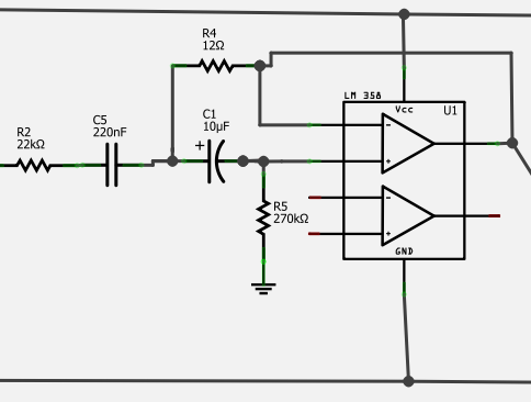
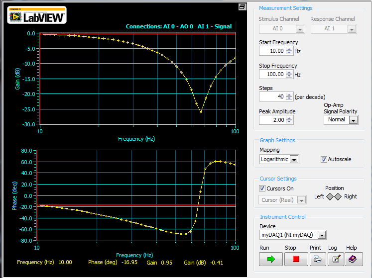
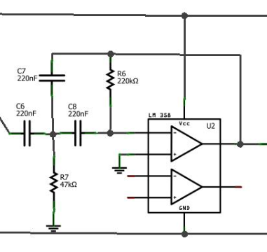
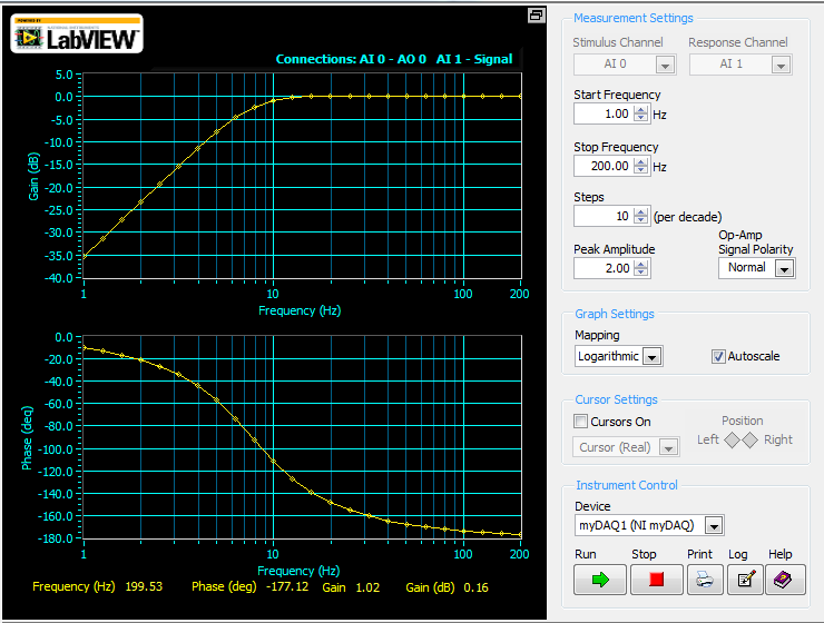
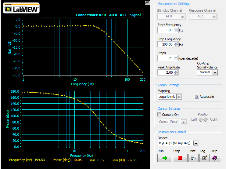
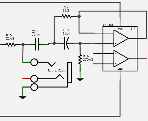
The attached picture is the final schematic. After the instrumentation amplifier, each box is a single op-amp (couldn't find a non-dual op-amp using this schematic program). I've also included the frequency response of the finished circuit (taken with the NI myDAQ, a good all-purpose oscilloscope) -- excluding the ~90x amplification the data receives by going through the instrumentation amplifier. For those not too familiar with dB, a nice conversion calculator with dB to linear gain/attenuation can be found here. Regarding power: the easiest way to power the circuit is with 2 9V batteries. To feed your op-amps -9V to 9V of power, connect one battery the correct way, and one backwards. That is, connect the positive lead of one battery to your positive power supply line and its negative lead to GND (ground). With the other battery, connect its positive lead to GND, and its negative lead to the negative power supply line. To "set" GND, you will eventually connect an electrode from your leg directly to the GND line. This will ensure that "0V" is your leg's voltage (unaffected by any head activity), and that all readings will vary from there.
The biggest design goal for this circuit is to obtain the data, then reduce noise by enough to get a good signal into the computer, where we will process the data a bit more. As we will be using our computer's sound card to get the data in, we have to cut noise enough that the signal with noise does not spike above or below +1V and -1V, as this is the point where the sound card clips the data off. As we will be using +-9V through batteries to power the circuit, we also have to make sure that as our data is going through the circuit, it never peaks above or below this value.
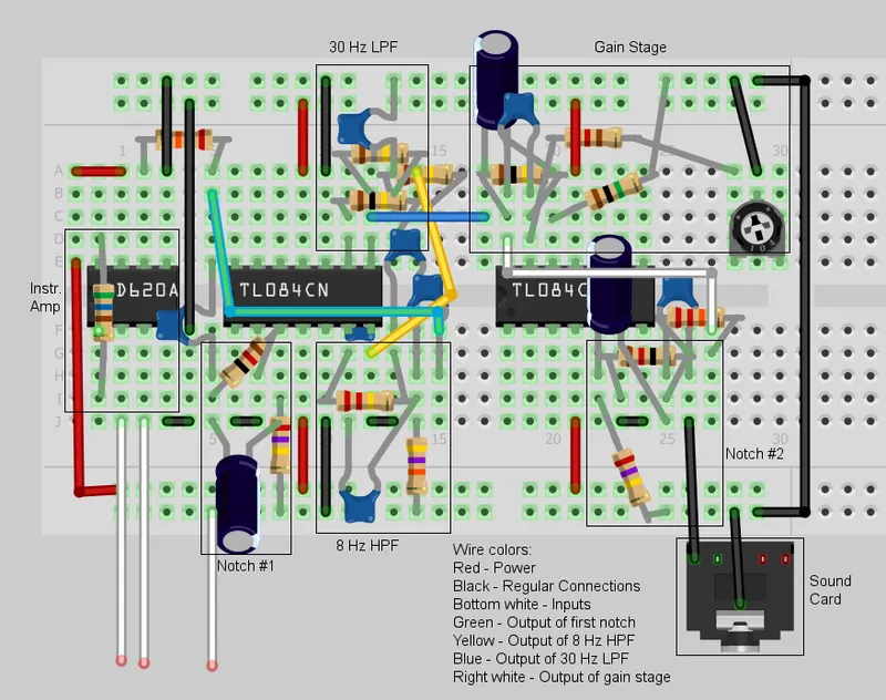
I've also included an example of how to lay out the components on a breadboard, one with notes on it and one without. It isn't exactly how I did it, but should give you a general idea if you haven't worked with breadboards before. Still, I do NOT suggest using that picture as a strict guide on how to wire everything. Follow the actual schematic -- the breadboard layout looks like a pretty jarbled mess (it gets really hard to avoid that when you try to fit everything on a 30-column board). The program also didn't always layer the components correctly, and since there's no way to test the "breadboard schematic", there's a possibility that it's not perfect. Use it as a general guideline, if you need it.
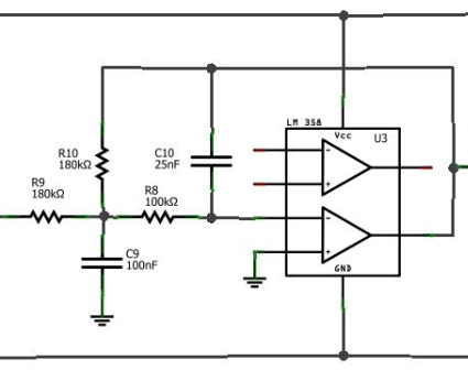
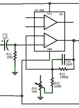
To clarify some specific colors used on the breadboard view -- all red wires are power lines, and all black are basic interconnections between circuit pieces (most are connections to ground). The green wire is the output of the first notch filter, the yellow is the output of the 8 Hz HPF, the blue is the output of the 30 Hz LPF, and the white wire is the output of the gain stage. The box at the bottom represents the audio cable going to the sound card.
In general, things to remember are that in breadboards the power lines (top and bottom rows) are connected horizontally, and the rest is connected vertically, with breaks in connections across the middle gap. When looking at the schematic, take care not to connect wires together unless a black circle is there with the connections - a cross without a dot doesn't indicate a connection.