Scupper R9 — Protective Kayak Transducer Mount | Lowrance TripleShot

Description
Scupper R9 — Protective Scupper Transducer Mount | Lowrance TripleShot
Short description
Four-part under-hull transducer mount using one M6 metal clamp through a compatible kayak scupper. Keeps a separate metal transom bracket, routes the cable beside the stud and includes a removable front cap. Four production STLs, fit coupons, ASA-CF starting projects and illustrated instructions. Hardware and transducer are not included.
Description
I wanted the transducer below the kayak without adding an external mounting arm. This design uses the scupper to clamp the mount from above while keeping a conventional metal transom bracket at the transducer.
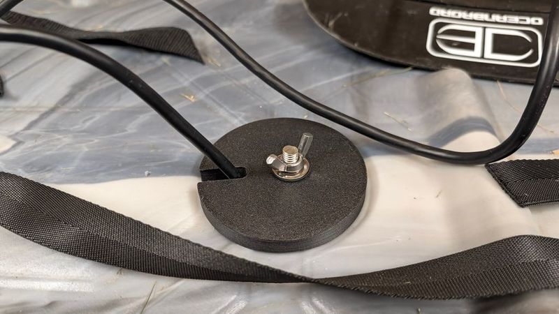
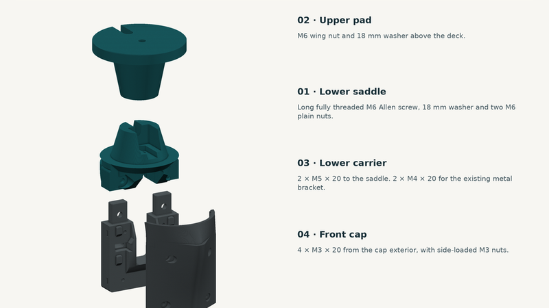
R9 uses a long, fully threaded M6 Allen-head screw instead of printed structural threads. The cable runs beside the screw in a separate channel. Two nuts retain the lower stud; routine tightening is done with the wing nut on top of the kayak.
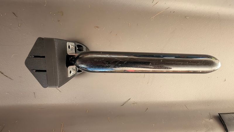
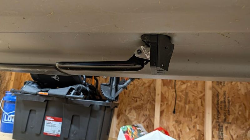
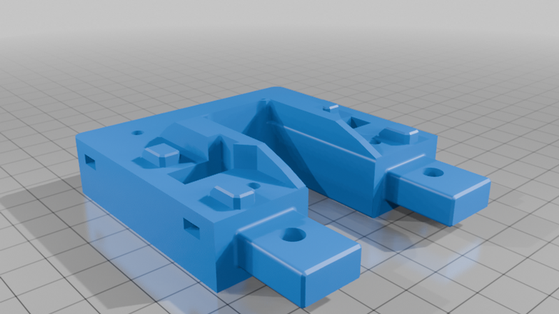
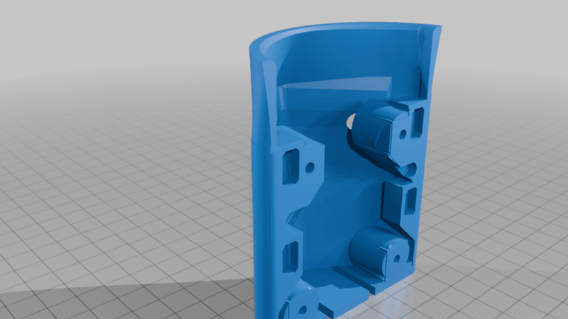
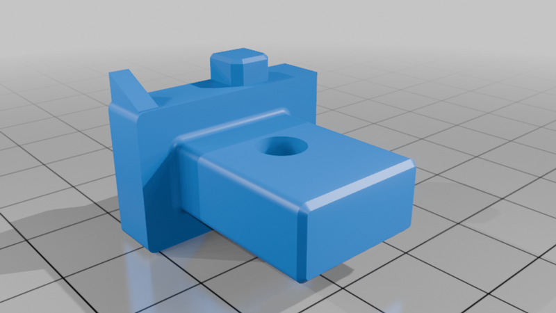
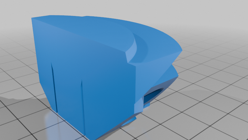
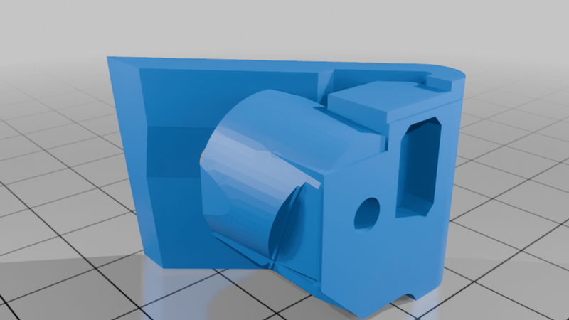
The lower assembly is modular. The carrier holds the transom bracket on its flat rear face, and the front cap comes off with four Allen screws. Removing the cap exposes the internal hardware without dismantling the main clamp. The supplied installation photographs show the actual arrangement rather than a reconstructed kayak or transducer.
Features
- One metal M6 scupper clamp with top-side wing-nut adjustment and separate cable routing.
- Retained metal transom bracket; 40–52 mm adjustment between its two M4 attachment axes.
- Four printable parts, a removable front cap and small fit coupons for the important interfaces.
- Metric socket-head hardware: M3 × 20, M4 × 20 and M5 × 20 for the lower assembly.
Included in the download
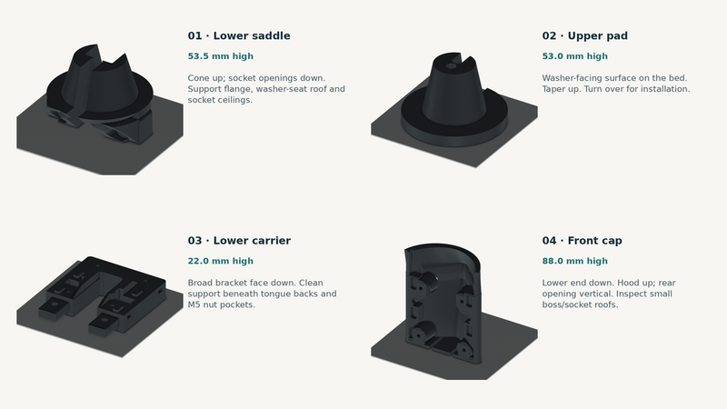
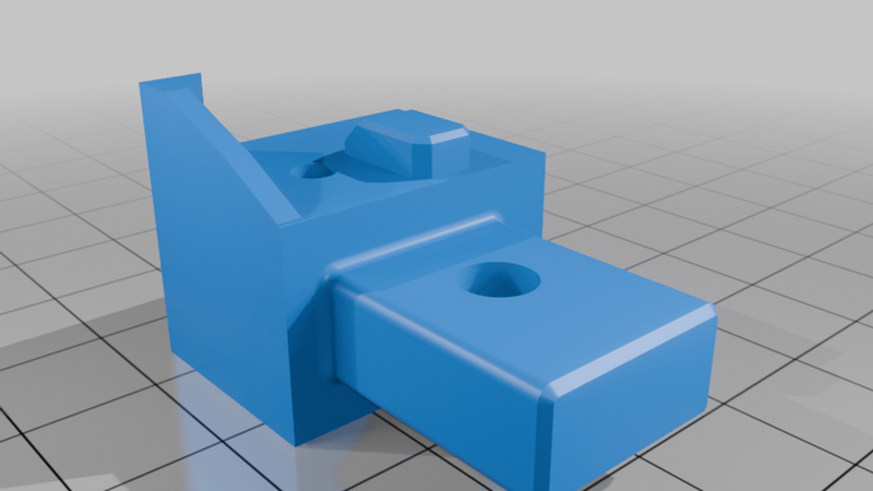
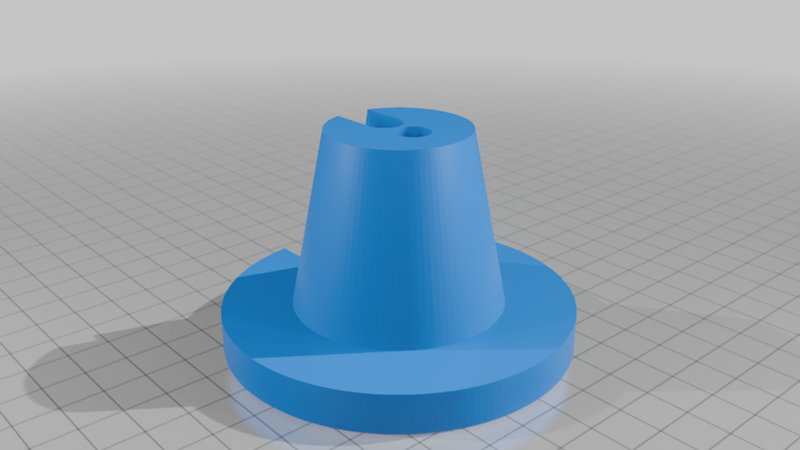
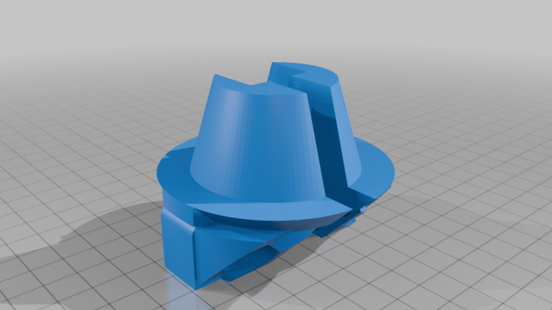
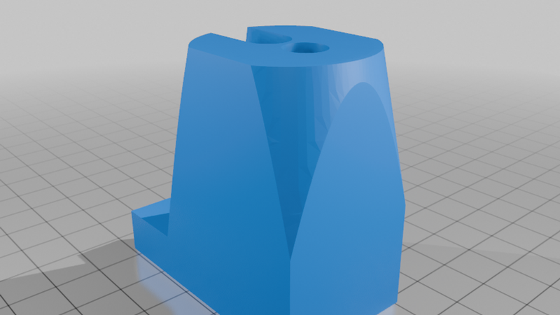
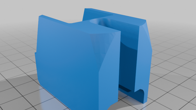
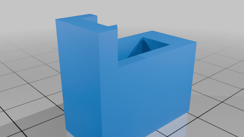
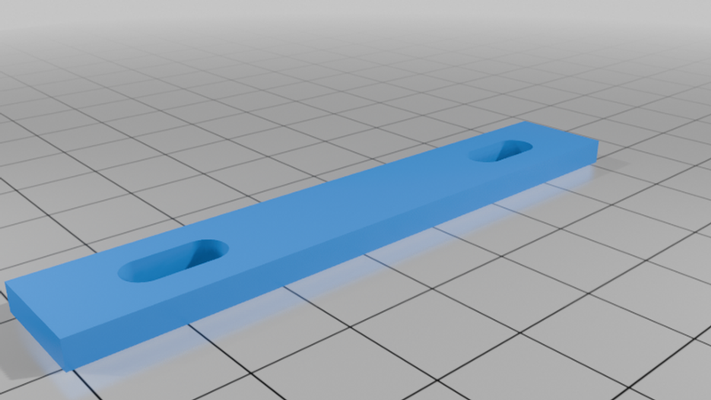
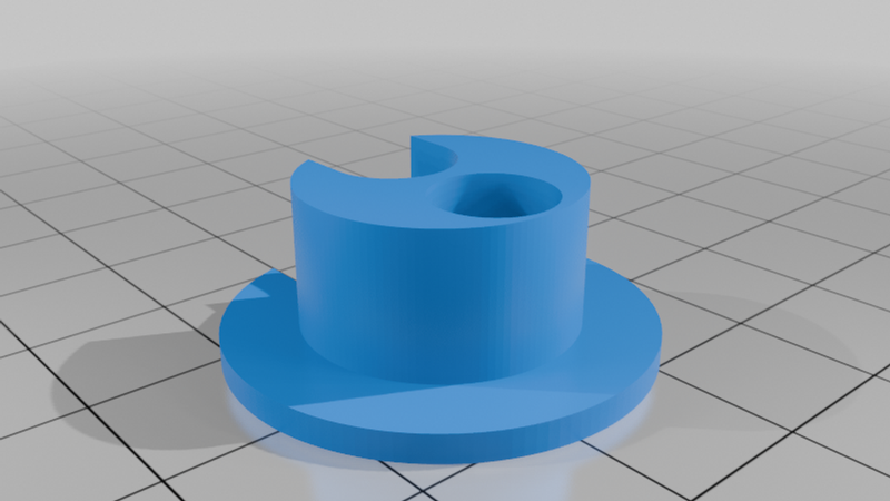
Four production STL files: R9 lower saddle, R9 upper pad, R8.4 lower carrier and R8.4 front cap. The R8p4 filenames are intentional; those are the parts used in the R9 assembly.
Also included: nine fit coupons, four unsliced Orca reference projects, a hardware BOM, bolt-length calculator, dedicated print and installation guides, a complete illustrated build guide, seven-view sheets and real installation photographs. The files retain their original scale and print orientations.
Not included: physical prints, filament, metal fasteners, transducer, metal bracket, pivot hardware, hull pads or protective tubing. No G-code is supplied.
Compatibility — check before printing
The owner reports a clean installed setup on a Pelican Catch Mode 110 fishing kayak, using a Lowrance HOOK Reveal 7 fish finder with a TripleShot transducer and a separate metal transom bracket. The bracket is installed in the owner’s reversed orientation, with a protective fin intended to deflect debris and oncoming water flow as the kayak moves forward. This protective function is a design intent; no measured drag, impact protection or sonar-performance improvement is claimed.
Other transducers may be adaptable using a suitable adapter that presents a mounting plane at 90° to the transducer itself. Such adapters are not included. Verify bolt spacing, cable clearance, operating orientation and the unobstructed sonar envelope for each transducer. This is not a universal-fit or stock-scupper compatibility claim.
Check the full scupper passage, the actual cable and sleeve, both hull-bearing lands and the complete bracket/transducer envelope. The model basis is a cable jacket up to 8 mm, sleeve OD up to 8 mm and an effective bearing span greater than 70.5 mm. A short 19.4 mm pilot gauge is included; passing it does not prove the whole installation.
The bracket's two bolt axes adjust from 40 to 52 mm apart. Confirm both feet sit flat and that the hull or cap does not block the transducer's required sonar view. No new hull-fastener holes are specified; do not force or enlarge a scupper to make the print fit.
Required hardware
Main clamp: one long fully threaded M6–1.0 socket-head screw, one M6 wing nut, two M6 plain nuts, two 18 × 6.4 × 1.6 mm washers, a smooth protective sleeve and fitted hull-contact pads. Measure the actual clamp stack before choosing screw length.
Lower assembly: 2 × M5 × 20, 2 × M4 × 20, and 4 × M3 × 20 socket-head screws, matching plain nuts and one washer under every head. Retain the metal bracket's original compatible pivot bolt, ratchet pieces and washers. The BOM gives the head, nut and washer dimensions that must fit the pockets.
Printing
The supplied starting process is FlashForge ASA-CF, 1.75 mm, hardened 0.4 mm nozzle, 0.20 mm layers, 255°C nozzle and 100°C bed on an Ender-3 V3 Plus. Use eight requested walls and 35% gyroid for the saddle, pad and carrier; six walls and 30% gyroid for the cap. Retain the main-clamp local solid modifiers.
Print the fit coupons first using the same material and process. Supports remain necessary at the lower saddle and carrier; the front cap has local boss/socket support concerns. Use the supplied orientations and inspect the actual sliced preview. The reference projects are unsliced starting points, not qualified print jobs. The manufacturer's material ranges and the complete support map are in the print guide.
Assembly and removal
Assemble the M6 stud on land. Install the carrier's M5 tongue nuts before inserting the tongues into the saddle, then attach the metal bracket with its M4 fasteners. Load the four cap nuts through the carrier's side openings and install the M3 screws from the cap exterior.
Pass the connector through the open scupper first, then lift the guarded stud beside the cable. Fit the upper pad, washer and wing nut and tighten from above after the bearing lands seat. For removal, support the lower assembly and undo the top hardware. The lower stud stays with the mount; no loose underwater nut or release pin is part of normal removal.
Limits
The supplied photos document an installed arrangement. No numerical working-load, tightening-torque, impact or endurance rating is provided. This is not a watertight plug, positive anti-rotation key, beaching skid or transport support. Check fit and alignment on the actual kayak, inspect after use and remove the mount for roof transport, beaching and dragging. Plain captive nuts are not self-locking.
Attribution
The inherited source credits digitalpowers, “Scupper Transducer Mount - Parameterized scad,” MakerWorld model 2820313. The original attribution and CC BY-SA notice are retained in the download. R9 uses the metal-clamp adaptation and the retained R8.4 bracket carrier/front cap. Named manufacturers do not endorse this model.
By Nate Maker 3D. Free digital download. CC BY-SA; retain attribution and share adaptations under the same license. AI assisted design/documentation; supplied real photos show the owner’s printed installation. Rendered assembly diagrams are identified separately.