Raspberry Pi 5 Enclosure: Finned Lid, Wall Mount and DIN Rail Clip (Heat-Set Inserts)
Description
A clean, support-free FDM enclosure for the Raspberry Pi 5, designed for real installs: desk, wall, or DIN rail.
Designed by elexResearch — embedded, RF and hardware engineering.
More projects and build notes: https://elexresearch.com
<a href=' https://elexresearch.com'>Elex Research </a>
Features
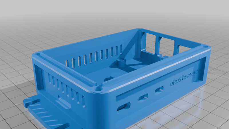
- Rounded body with recessed side panels for a stiff frame and a clean look
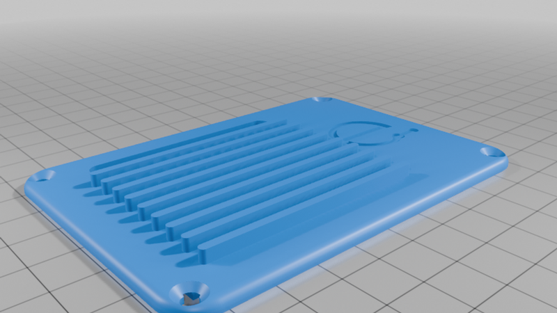
- Heatsink-style finned lid with vent slots over the Active Cooler and an open GPIO channel
- Tight rounded port openings: USB-C, 2x micro-HDMI, 2x USB stacks, Ethernet, microSD
- M3 heat-set inserts throughout, no screws threaded directly into plastic
- Countersunk M3 lid screws that sit flush with the top
- Wall-mount ears with open M3 slots on both ends
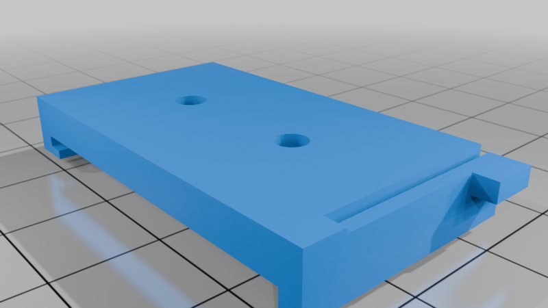
- Optional snap-on TS35 DIN rail clip that screws to the base
- Parametric FreeCAD source available
Parts
- Base: print upright, floor on the bed. No supports needed.
- Lid: print top-up with the flat underside on the bed. No supports needed.
- DIN clip (optional): print as oriented in the file. PETG recommended for the spring latch.
Hardware
- 8x M3 heat-set inserts for 4.0 mm holes, max 5.7 mm long (lid posts and board standoffs)
- 2x short M3 heat-set inserts, 4 mm long (DIN clip pads, only if you use the clip)
- 4x M3x8 countersunk (lid)
- 4x M3x6 pan or button head (Pi to standoffs)
- 2x M3x8 countersunk (DIN clip)
- Wall: M3 bolts with nuts for panels, or 3–3.5 mm wood screws with plugs for masonry
Note: the Pi 5 mounting holes are 2.7 mm. M3 board screws need the holes opened to 3.2 mm. Use M2.5 screws if you prefer not to drill.
Assembly
1. Install the heat-set inserts.
2. Remove the microSD card.
3. Lower the Pi in about 2 mm toward the microSD end, then slide it toward the USB/Ethernet end so the jacks seat in their openings.
4. Screw the board down, fit the lid, and add the DIN clip if needed.
Fit note
Before committing to a full print, test-print the USB/Ethernet end wall to check port fit on your printer.
Questions or custom enclosure work: https://elexresearch.com