UniFi SuperLink Gateway Wall Mount — Hidden Ethernet Cable
Description
UniFi SuperLink Gateway Wall Mount — Hidden Ethernet Cable
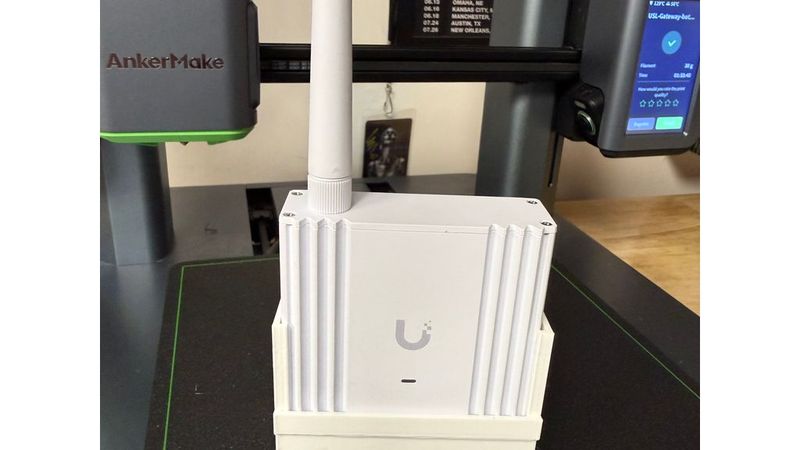
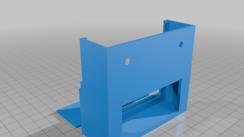
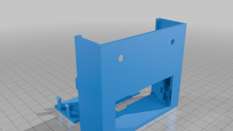
A compact, 3D-printable wall mount for the Ubiquiti UniFi SuperLink Gateway (USL-Gateway). The gateway slides in from the top, with an enclosed lower chamber hiding the Ethernet/PoE connector and a rear opening routing the cable into the wall.
The front remains open so the status LED is visible. Thin side wraps with retaining lips and a small bottom band hold the gateway in place.
Features
- Top-down slide-in installation and lift-out removal.
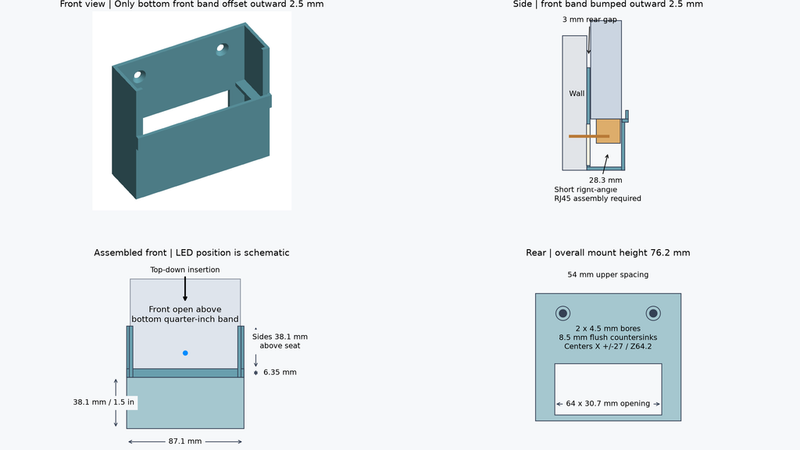
- Approximately 3 mm clearance between the gateway and wall.
- 1½-inch-tall enclosed cable chamber beneath the device.
- ¼-inch front retaining band, offset outward to clear the gateway’s fins.
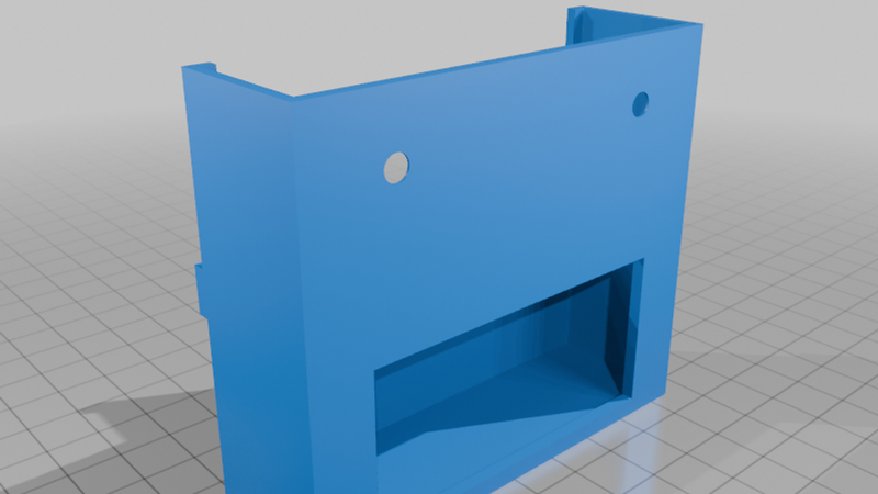
- Two upper countersunk wall screw holes.
- Editable, parametric OpenSCAD source included.
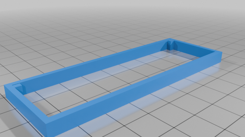
- Small fit-test coupon included.
Printing
Suggested starting settings:
- Material: PETG
- Layer height: 0.20 mm
- Walls: 4 perimeters
- Top/bottom layers: 5
- Infill: 20–30%
Print upright with the flat bottom on the bed. Use local supports beneath the internal device seats and projecting bottom-band rim. Check overhangs in your slicer and remove supports before assembly.
Print the fit coupon first. Printer tolerances and the gateway’s fin geometry can affect fit.
Installation
Remove the original mounting bracket before inserting the gateway. Feed the Ethernet connector through the rear opening, then secure the mount using two suitable flat-head screws and wall anchors. The screw holes are 4.5 mm diameter with 8.5 mm countersinks, spaced 54 mm apart. Screw heads must sit flush.
Connect the gateway above the mount, then slide it down onto the internal seats while guiding the cable into the wall. Leave enough cable slack and clearance above the gateway for removal.
Cable Clearance
The rear cable opening measures approximately 64 × 30.7 mm. A low-profile right-angle RJ45 connection is the intended arrangement; check your connector’s dimensions and orientation before printing.
The wall opening and cavity must provide enough room for the cable route. The mount does not guarantee clearance for every straight plug, boot, or cable bend.
Dimensions and Files
Overall dimensions: approximately 87.1 mm wide × 76.2 mm tall × 30.8 mm maximum depth.
Included files:
- Full mount STL
- Fit-test coupon STL
- Parametric OpenSCAD source
The design was refined using printed-fit feedback. The latest bottom-band clearance adjustment still needs physical verification. STL mesh checks passed.
Designed for indoor use. This is an independent accessory, not an official Ubiquiti product.