Reverse-Twist 4-Lug Bayonet Lock Mechanism

Description
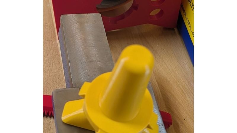
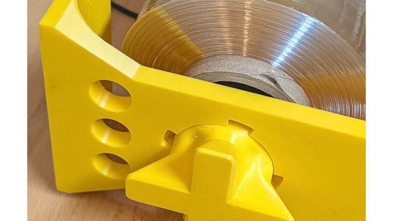
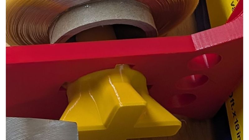
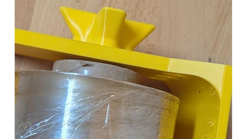
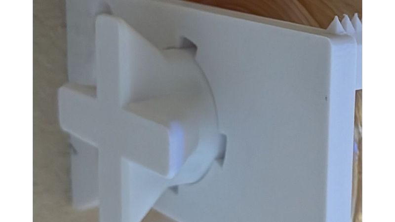
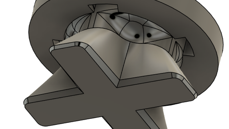
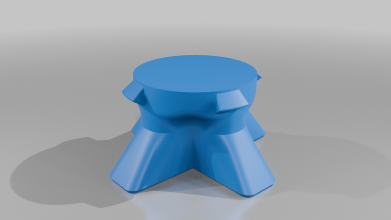
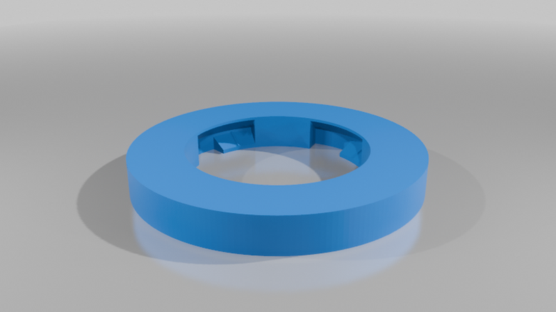
Reverse-Twist 4-Lug Bayonet Lock Mechanism (STEP & 3MF) by Torque Joint Labs
⚠️ IMPORTANT NOTE: This specific model features a Counter-Clockwise (CCW) Locking Action (lefty-tighty, righty-loosey). Twisting the male plug to the left pulls it into the locking detents, making it ideal for specialized rotary applications or setups where standard clockwise torque would accidentally loosen the joint.
A robust, positive-locking bayonet / twist-lock mechanism designed specifically for functional 3D prints, custom enclosures, modular mounts, and utility fixtures.
Instead of relying on fragile friction fits or prone-to-stripping threads, this connector uses four ramped camming lugs with integrated detents to pull mating components together tightly and lock them securely with a short, deliberate quarter-turn to the left.
Features & Engineering Specifications
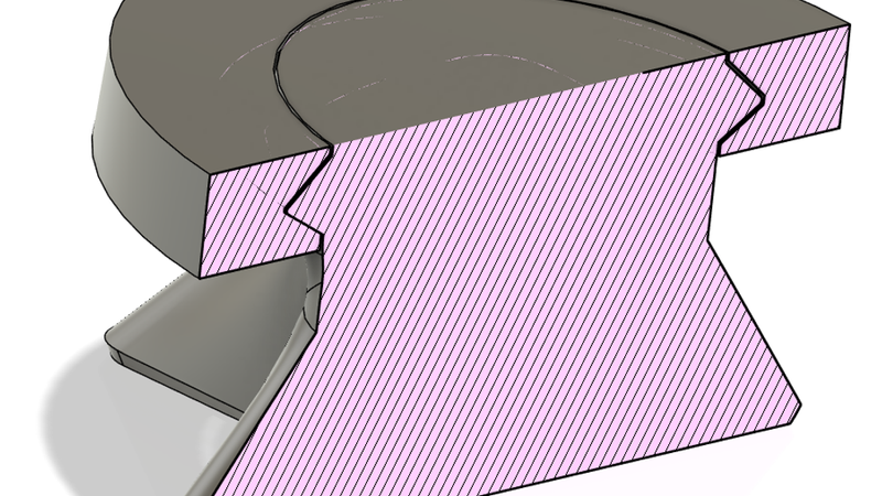
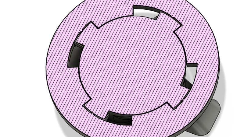
* Reverse-Twist Camming & Detent: Ramped female channels pull the assembly into compression before snapping into a positive detent pocket when twisted counter-clockwise, preventing vibration-induced back-off.
* Nominal Interface Diameter: 50 mm (female inner bore Ø50 mm, male shaft Ø49.4 mm).
* Support-Free Asymmetric Geometry: The internal locking geometry utilizes asymmetric 30° and 40° angled surfaces.
* Built-in FDM Tolerances: Pre-cleared 0.3 mm radial clearance between sliding surfaces to ensure smooth rotation straight off the build plate without post-processing.
* 4-Lug Symmetric Engagement: Four balanced locking lugs (11 mm nominal width) distribute rotational and axial pull loads evenly across the perimeter.
Recommended Print Settings
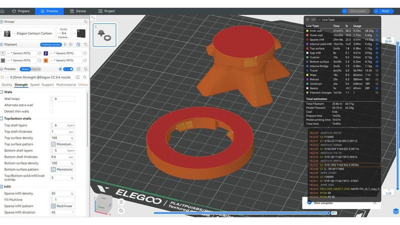
Both components are fully optimized to print without supports and require zero post-processing when oriented correctly:
* Orientation:
* Female Collar: Print insert-side down. This prevents the shallow 30° angle from being an overhang, leaving only the steeper 40° angle which prints cleanly without supports.
* Male Core: Print flat on the build plate. The lug overhangs are angled to bridge cleanly without support structures.
* Perimeters / Walls: 5–6 walls (critical for shear strength on the locking lugs).
* Top & Bottom Layers: 5 top, 5 bottom.
* Infill: 20%–40% (the standard strength settings in Elegoo Slicer do just fine).
* Layer Height: 0.16 mm – 0.20 mm (finer layer heights produce a smoother camming action along the ramps).
* Recommended Materials: ASA, PC-CF, or PETG for functional mechanical durability and repeated twisting; PLA works great for prototypes and light-duty indoor brackets.
Remixing & CAD Integration (STEP Files Included)
This mechanism is designed to be a building block for your own projects, and remixes are highly encouraged! I have included the raw .STEP files alongside the 3MFs so you can easily edit the geometry without dealing with messy STL mesh conversions.
How to add this locking joint to your own designs:
1. Import the provided .STEP file into your CAD package (Fusion 360, Onshape, SolidWorks, Creo, etc.).
2. Customize the Handle: The included 4-finger cross-handle on the male plug is very robust, but you can easily slice it off in your CAD software and model your own custom handle or grip to fit your specific needs.
3. Align the female ring or male core wherever you need a quick-release connection.
4. Perform a Boolean Subtract / Combine Cut against your target model.
5. Keep the original tool body if you need to retain the standalone mating plug.
If you integrate this into a custom tool holder, shop vacuum manifold, or storage container, please post it as a remix!