SPLOS65 V0.2 Tiny Whoop with top mounted LiPo (FATAL ERROR will be deleted)

Description
Read this before going to the intro : My support for it has ended !
Page will be deleted when uploading V0.3 on a new page
REASON 1 FOR MY END OF SUPPORT: FATAL ERROR
I discovered fatal design flaw for SPLOS65 V0.1 V0.2. 😨 Motors with 1.0 mm shafts use an M1.2 C-clip, which can actually have a diameter of up to 2.8 - 3.2 mm. I designed the hole to be exactly 3.2 mm. This is to much at the limit... I'll revise it over the next few days. So, it's being delayed...
Intro
Name: SPLOS65 V0.2 Tiny Whoop with top mounted LiPo (test phase)
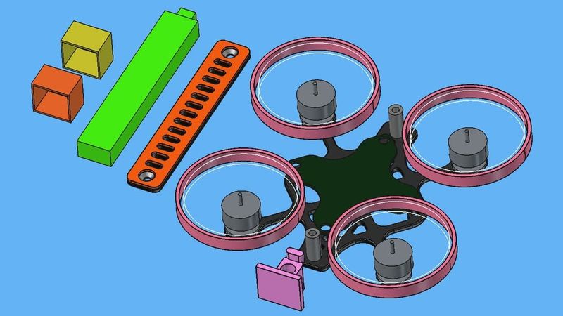
* For FPV and LOS. The name stands for SPLOS (Smallest Possible LOS). For the smallest standard drone parts and LiPo. It can also do FPV. SPLOS aka SPFPV. The design was originally intended only for LOS but it turned out that it should work well for FPV too. I kept the name SPLOS.
* Prop guards cuted out from any classic Tiny Whoop.
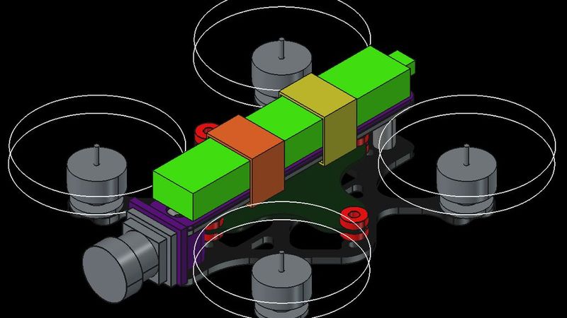
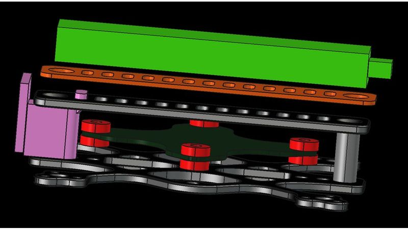
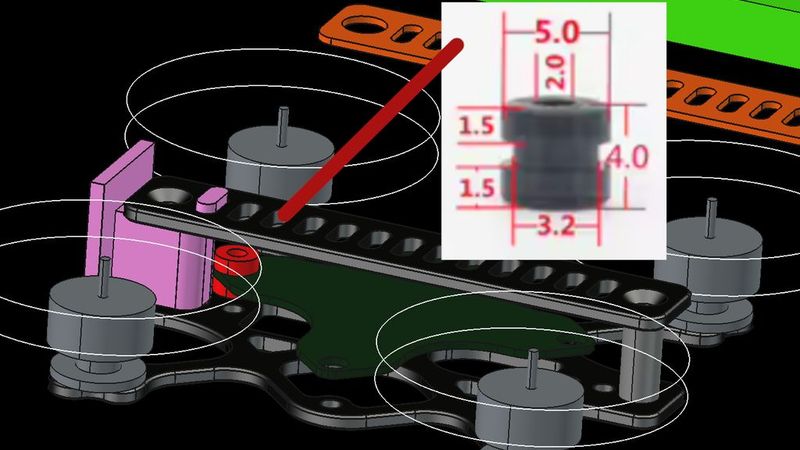
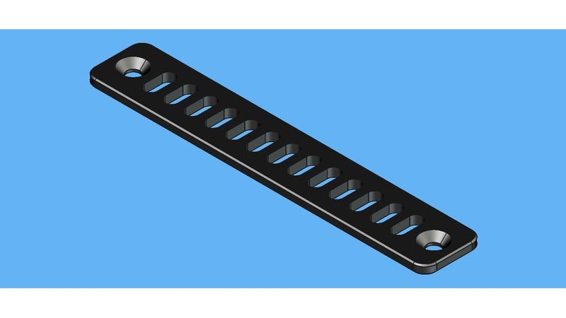
* LiPo secured with rubber bands. These can be replaced/repaired if you remove the top plate.
* The FPV cam mount still needs some work (You're welcome to join in) . The basic foundation is in place. Tilt can also be added.
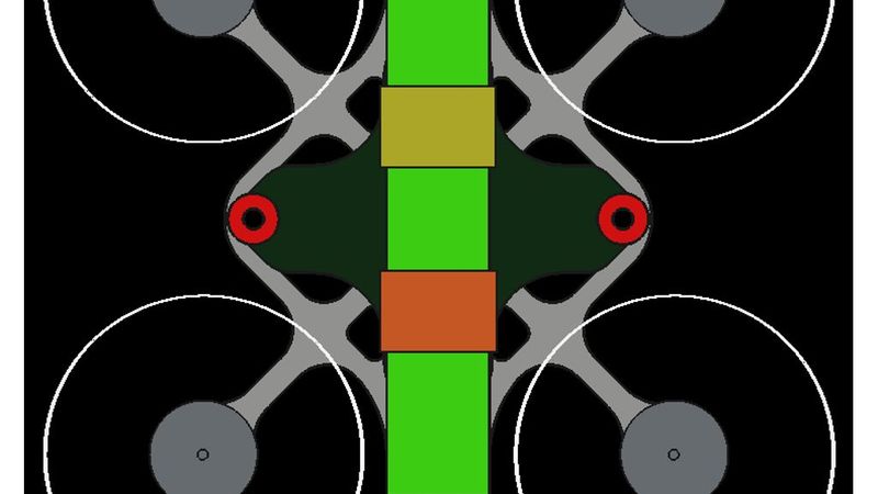
* Three possible configurations: 1) Top mounted LiPo 2) Top mounted LiPo Pusher 3) Bottom-mounted LiPo, in which case the top plate can be omitted. See also SPLOS V1.0 for images of the configurations. SPLOS V0.1: https://www.thingiverse.com/thing:7361570
*
Main specifications ( Specs )
X-shape: True X
Wheelbase: 65 mm (64.997261481... mm)
Motor to motor: 45.96 mm
Motor compatibility: For D6,6 M1.4 mounted motors (Classic 65 mm Tiny Whoop motors ...)
Motor central hole (for shaft and ring) on frame: 3.2 mm
(Take car not all motors fit into that 3.2 mm motor center hole, for example Happymodel SE0802 not. Normally only the C-clip protrudes at the bottom with highest diameter, and it has a standardized diameter of 2.2–2.6 mm for a M1.2 C-clip for a 1.0 mm shaft; washers for these motors generally have a maximum diameter of around 2.8–3.0 mm. Little amount of motors have a 5.0 mm centering collar, they simply don't fit on this frame.)
Motor recommended for ACRO/AIR mode: 0702/0703/0802
Motor recommended for 3D mode (expected Gemfan 123D prop 1.0 mm): 0802.8/0803
Battery optimal size: 280mAh LAVA II 54x10x6
Battery recommended: 280mAh LAVA II 54x10x6 mm - 320mAh LAVA II 64x10x6 mm and older 1S 300 mAh LiPos.
Battery in demonstration pics: 280mAh LAVA II 54x10x6 mm
Bottom plate carbon fiber thickness : 1.5 mm
Weight theoretically: Approx 2.42 g
Top plate carbon fiber thickness: 1.5 mm
Weight top plate theoretically: Approx 1.03 g
*
This is a free download of a complete drone frame
Free download of this COMPLETE drone frame !
It is not 100% open source because i do not provide my FeeCAD project file for easy modification on the design.
*
Buy immediately
You can buy my designs at:
Sugalime3D FPV Zero Design Fee Shop at Armattan Productions Made in ROC (aka Taiwan):
https://www.armattanproductions.com/pages/shop_product_grid/10788
Coming soon
https://www. ...
Further down, under the headings "Carbon fiber services" you can find alternative ways to purchase it.
THIS IS NON-PROFIT MOTIVATION !
This isn't an advertisement for these companies ! I receive zero revenue through that ! The reason my frames are here is that the provider makes it very easy to set up your own shop or sell my designs to my followers and interessted people. My motivation is not profit but showing new design ideas i wish for the market.
*
Timeline
Check regularly for updates. More parts will likely be added if the tests are successful (TPU parts, carbon fiber parts, ...) !
* September 28, 2026: Publication date with basic parts
*
Some of the features of this frame explained
Orientation on real values rather than imprecise specs
Explanation
It looks like the manufacturer only lists the width of the LiPo battery itself, not the width of the connector housing used for the BT2.0—which is actually wider than the battery. Manufacturers and brands often aren't very good at providing complete and precise dimensional specifications.
Tiny Whoop 1S LiPo sizes : Measured w. entry-level elec. metal caterpillar:
BETAFPV 1S 280 mAh LAVA II (Their spec 54x10x6 mm)
Max width: BT2.0 connector attached body cover to LiPo: 12.49 – 12.56 mm (relatively tightly compressed)
Max length: Including BT2.0 body cover (excluding BT2.0 male connector part): 54.4 – 54.9 mm
Horizontal standoff frames (Muffle31 drone frame) => Standard M2 standoff 13.5 mm
BETAFPV 1S 320 mAh LAVA II (Their spec 64x10x6 mm)
Max width?? Probably 12,57 mm as well
Max length: ??
Horizontal standoff frames (Muffle31 drone frame) => Standard M2 standoff 13.5 mm
BETAFPV 1S 300 mAh 2022 version (Their spec 67,3x11.8x6.1 mm)
Max width: BT2.0 connector attached body cover to LiPo: 12.56 – 12.58 mm (when squeezed relatively firmly)
Max. length: Including BT2.0 body cover (excluding BT2.0 male connector part): 63.3 – 63.8 mm (so, max. 63.8 mm)
Horizontal standoff frames (Muffle31 drone frame) => Standard M2 standoff 13.5 mm
Designed to international standards
Based on DIN EN ISO 7721 and ISO 10642. And close fit (not normal fit) with screws MX regular (not MX fine).
M3 screws ISO regular M3x0.5:
Screw Clearance M3 Holes: 3.20 mm (clearance close 3.2 not medium 3.4 mm)
M3 90° Countersink: 6.50 mm diameter (not the theoretical max of 6.94 mm)
(with FreeCAD PartDesign_Hole, ISO regular, clearance setting close/fine, results in 3.2 mm hole)
M2 screws ISO regular M2x0.4:
Screw Clearance M2 Holes: 2.20 mm (clearance close 2.2 not medium 2.4 mm)
M2 90° Countersink: 4.40 mm diameter
(with FreeCAD PartDesign_Hole, ISO regular, clearance setting close/fine, results in 2.2 mm hole)
M1.6 screws ISO regular M1.6x0.35:
Screw Clearance Holes: 1.70 mm (clearance close 1.7 not medium 1.8 mm)
M1.4 screws, ISO regular M1.4x0.3:
Screw Clearance Holes: 1.50 mm (clearance close 1.5 not medium 1.6 mm)
*
CNC service for the carbon fiber parts
Right at the top of the intro, you’ll find a way to order it immediately. Alternatively, you would need to submit a request to a CNC service. You can give the CNC service your selected STEP files; it contains all the information, including details about the plate thickness and chamfers. Here are further explanations on how to proceed:
Design for Manufacturing
The project was designed with the practical CNC process in mind to ensure the CNC service faces no difficulties and can cut the part quickly and cheap—for example, through a design that is as simple as possible (balancing functionality and simplicity), large fillets, minimal chamfering, ... And international standards for MX holes.
List of services
(No guarantee of legitimacy, these are all the ones I found, not the ones I tested.)
List of all I know:
* Made in Canada: CNCdrones dot com; CNCMadness dot com; ...
* Made in France: FPVCNCdrone dot com; ...
* Made in Germany: Ahltec dot de (Inh. Angelika Leonhardt); carbonforce dot de (CarbonForce® GmbH), carbon-composite dot com (Carbon Composite AG); carbon-express dot com (CARBON-EXPRESS GmbH), carbon-posten dot de (Inh. Sandra Schmidt); cg-tec dot de (CG TEC Carbon und Glasfasertechnik GmbH); ...
* Made in People's Republic of China (aka Mainland China aka China): CK-Carbon Fiber Store (Aliexpress store ID 1104334140 or search for 1005012382499688 (item)); corewell-cnc dot com (Corewell CNC Manufacture Limited); FPVdroneframe dot com; pcbway dot com; ...
* Made in Republic of China (aka Taiwan): armattanproductions dot com (Armattan Productions Co., Ltd); ...
Carbon fiber material international standards
Choose what you consider the best sweat spot for your purpose or choose T-800S if money is not a factor to be considered.
Tensile strength is the factor when it comes to arm breaking. Tensile modulus (stiffness) is the factor for vibrations and resonances that can be transmitted to the gyro.
* T-300: Tensile strength: ~ 3530 MPa. Tensile modulus (stiffness): ~ 230 GPa. The affordable and most used standard.
* T-700S: Tensile strength: ~ 4900 MPa. Tensile modulus (stiffness): ~ 235 GPa. Used on expensive high-quality premium frames.
* T-800S: Tensile strength: ~ 5685 MPa. Tensile modulus (stiffness): ~ 294 GPa. Consumer ready in the future. This aerospace and commercial aviation standard is becoming affordable for the consumer hobby market. By now, some very expensive premium drone frames actually use it.
Plate rotation for carbon fiber pattern matching orientation of the arms (turned45XY label)
For the bottom plate use the STEP or STL file labeled "turned45XY" so that the carbon fiber rectangle pattern runs parallel to the drone frame arms. Then the CNC manufacturer should normally position them correctly using this STEP files. Top plates are generally already oriented correctly so that the carbon fiber pattern aligns properly with the part. Therefore, there is no "turned XY" version for these. Or use for bottom plate the non labeled if your CNC process is different.
ADVICE FOR MYSELF THE DESIGNER (so i never foget in future project exports): In FreeCAD the STEP export has to be saved with "Export single object placement" otherwise it won't be rotated by 45° if the FreeCAD transform feature (with Right click in the tree on the body) was used later !
Fillets
The fillets are always chosen to be as large as possible (better for durability) and never have a radius below 0.50 mm (standard milling heads have a minimum limit).
The smallest fillet radius used in this project:
Outer fillet: X mm
Inner fillet: 1.2 mm
So it can be milled with a D2.4 mm CNC theoretically (not recommanded), D2.0 mm CNC practically (should work well).
Why fillets always need to be slightly larger than the drill diameter you want to use:
If the milling cutter matches the inner corner radius exactly, the tool tends to "wrap around" the corner (increased wrap angle). This can lead to vibrations or tool deflection. If tolerances allow, it is often advantageous in CNC milling to specify a slightly larger inner radius in the CAD model; this allows the cutter to navigate the corner smoothly rather than having to change direction abruptly...
The minimum inner corner fillet is selected as follows :
* R 1.2 mm D 2.4 mm (2.0 mm cutter with 0.2 mm clearance every side)
* R 1.45 mm D 2.9 mm (2.5 mm cutter with 0.2 mm clearance every side)
* R 1.7 mm D 3.4 mm (3.0 mm cutter with 0.2 mm clearance every side)
* R 1.95 mm D 3.9 mm (3.5 mm cutter with 0.2 mm clearance every side)
* R 2.2 mm D 4.4 mm (4.0 mm cutter with 0.2 mm clearance every side)
...
This makes it possible to always use the largest possible milling cutter. This speeds up the CNC job, thereby making it more cost-effective...
Chamfer editions & Edition labels
The chamfers are important to prevent the electric cables, the LiPo straps or your fingers skin from being cut.
4 labels
* NC NCS: Edition is without chamfers and without countersinks. This edition is only available if a Designer's Edition with countersink exists for the part. Advantage: Requires the least milling work. The cheapest option.
* NC: Edition is without chamfers (NC = No chamfers) Advantage: The (second) cheapest option.
* OPCO: Edition is with "Outer Perimeter Chamfered Only". Requires often only a bit more milling work using a buck side chamfer mill.
* NORMAL (Non labeled): It is the designer's version "Director's cut" . Like the designer wishes it to be. Version includes maximum of meaningful chamfers. Disadvantage: A part with a lot of chamfers on both sides can be very expensive especially when holes or radii are small, depending on the capabilities of the CNC manufacturer. The effort and time involved in the milling process can increase significantly. Consequently price can be 2-3x higher than that of the NC NCS version. Sometimes the OPCO edition already is the designer's edition.
Buck side chamfer CNC process
The CNC service typically creates the double sided chamfer using a special drill head (buck side chamfering) that first makes the chamfer on top then on the bottom, or they use a high accuracy plate turning process if the holes are too small for the special drill.
Public example of buck side chamfering
https://www.youtube.com/shorts/9M66unswJ7c
Creating round edges without chamfer milling
The sharp corners can also be rounded off without milling chamfers: They place the part in a in a tumbling drum and they use a sharpening stones tumble vibratory deburring method, or they use other methods to remove the corners sharpness. However, the corners aren't rounded off as much with this method—especially if the manufacturer does not give it a lot of time to it. The edges remain relatively sharp and it doesn't match the quality and smoothness of chamfer milling. COSTS: Sometimes rounding the corners like this is cheaper, sometimes milling the chamfers is cheaper—it depends.
*
Development timeline
Future
Planned changes in the future (next version)
* No
History
SPLOS V0.1:
https://www.thingiverse.com/thing:7361570
*
This is not a professional product (it is an hobby drone frame designer hobby project)
Use at your own risk ! It is not released in a 1.0 version because I cannot guarantee that it is already a mature well testet product.
I guess it should work. Big and/or small errors are possible. The design is still in the prototype and test phase. Therefore, the project may still be revised and then appear as higher version number on a new page. If the tests are successful this allready is the final version of the project.
Tests so far
1) Everything fits using 3D CAD multibody modeling. Double verification of measurements with 3D CAD catapillar: YES
2) Designer ordered it at a CNC service:
3) Designer received it. Eye test and a light bending test with fingers was successful:
4) Verification of all measurements with real catapillar:
5) Build process using Motors and electronics was without problems:
6) First flight tests without problems:
7) Many flight tests and crashes without problem:
Used 3D CAD software
FreeCAD
Thanks to everyone involved in FreeCAD for allowing me to use it for free and without any restrictions.
*
Copyright & Credits
PRIVATE USE:
You are allowed to download and copy and modify the frame for private use and upload and publish a CAD mod/remix with credits (My name and the link to this one); please note the license terms specified below.
Videos or picture in the internet, me or the name of the frame I don't expect to be mentioned in videos or pictures or description.
COMMERCIAL USE:
I permit to download and use and copy and modify for commercial sales. However, I expect the designer name and product name to be mentioned in the title or description of the product with the product name: "Design name" and the designer name :"Sugalime3D FPV" or "Sugalime3D FPV design" or "designed by Sugalime3D FPV".
Examples:
[Your Brand] Sugalime3D FPV Design name
[Your Brand] Design name Sugalime3D FPV
*
Liability for negative consequences from the use
This CAD design is provided 'as-is' for community and open-source use without any warranty of any kind. The designer assumes no liability for any direct, indirect, or consequential damages (physically as well as financially) resulting from the manufacturing, assembly, or the use of this frame design.