OG Xbox System-Link Enclosure
Description
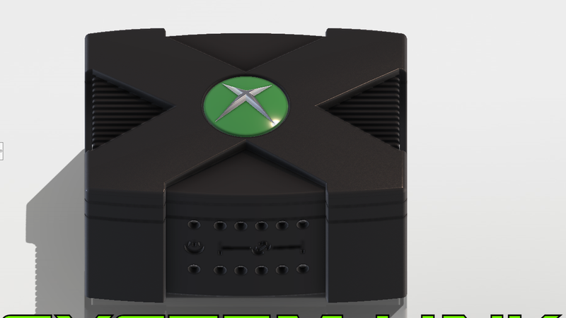
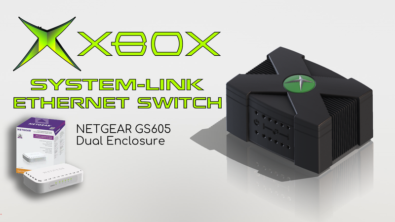
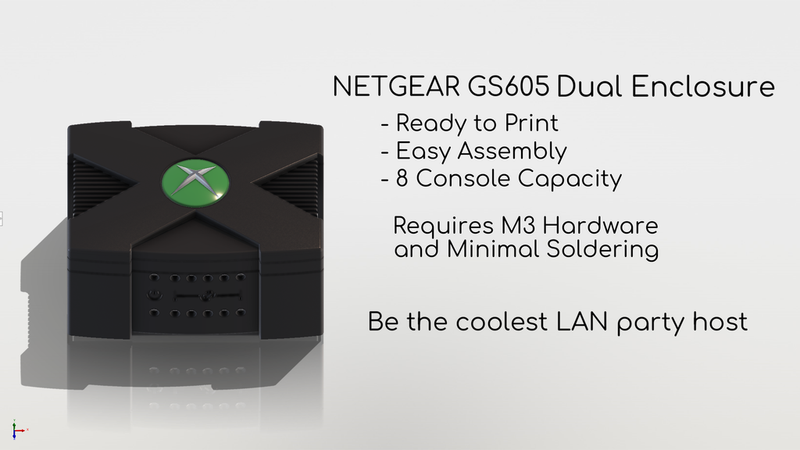
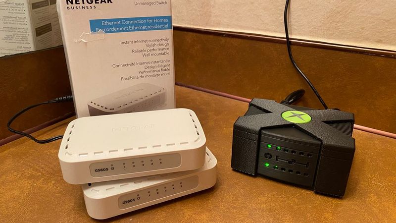
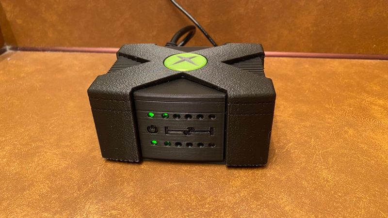
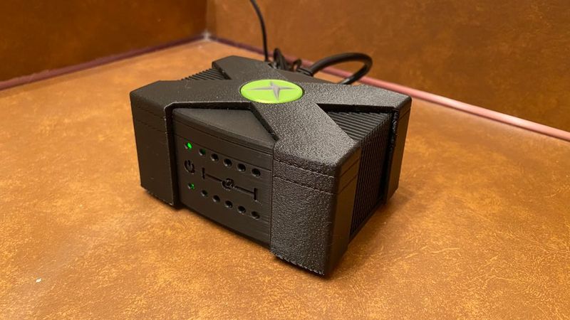
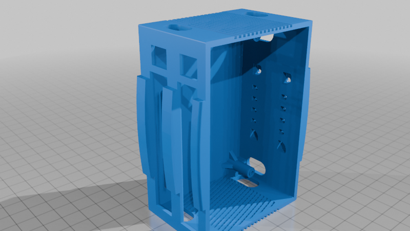
A custom enclosure for two NETGEAR GS605 5-port ethernet switches, designed to look right at home next to your original Xbox console during your next LAN party!
Background:
I recently picked up two GS605 ethernet switches on clearance for a possible system link LAN party, and I took it upon myself as a fun challenge and a refresher on my CAD skills to design this themed enclosure for them. My two goals for this project was to design an homage and accessory to one of the best parts of early 2000's gaming, the LAN party, and to combine my two switches into one board and run off a single power supply, to cut down on cables being run across the room in the case of such an event. Now, would having two separate ethernet switches you could daisy chain together with a long ethernet cable to span multiple rooms be a more reasonable setup? In most cases, yes. HOWEVER, I am not a reasonable man, and rule of cool beats all.
Printing Tips:
I tried to keep the limitations of 3D printing in mind while designing this enclosure, but a few items I deemed looks far more important than printing optimization, so heres a few notes I had for making the thing.
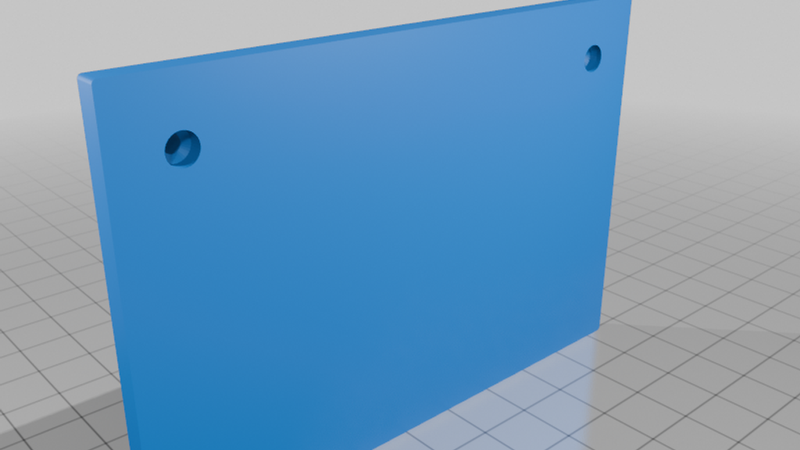
BasePlate - just print with the flat side down, screw holes are already chamfered for supportless printing
InnerShell - The most optimized part of the enclosure. Print closed side down, should work without supports, but if issues are encountered, minimal supports for surfaces with an overhang angle just shy of 60 degrees is recommended (helps with the LED diffuser holes while not generating support for cooling slats)
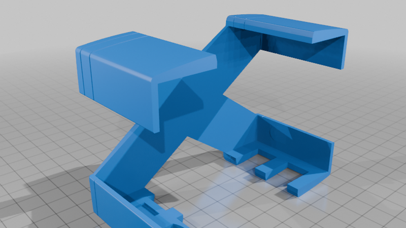
OuterShell - Here's one that's gonna take some tweaking, you could print it face up or down with minimal supports, but I found best quality when printing at about a 30-40 degree angle with a good structure of supports, so that the slight curvature of the 'X' gets the highest quality print lines.
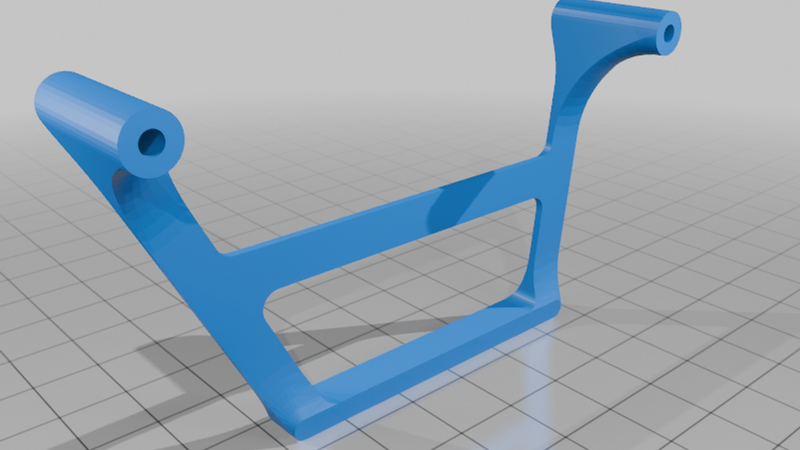
Riser - Another to print at your discretion, I recommend printing with the flat ends of the screw posts down, definitely print with supports.
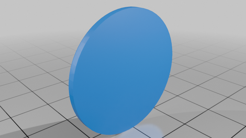
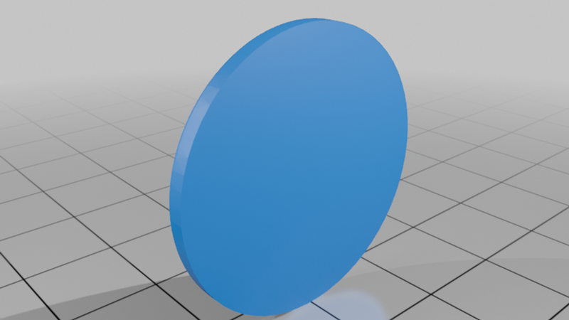
Center Gems (rounded or Flat) - Print these however you want, Flat is the easiest and quickest to print, with Round being better to print at an angle for high quality curvature print lines, .STEP files provided to allow for multi-color printing of the X if your slicer and printer support it.
Assembly Instructions/Tips:
Quick and easy assembly was forefront in my mind during designing this thing, so aside from some basic and common M3 Hardware (2 long screws and 2 Short) it mostly clamps together, but there is an order to how to assemble it.
Harvesting the Boards - Easy job, simply open the original GS605 enclosures and gently pull the board up being cautious of clearing the ethernet ports from their enclosures hole.
Harvesting the LED diffuser - You can gently pry the clear plastic LED light diffusers from the shell with a pair of pliers, my design uses these parts unmodified.
Soldering Barrel Jacks - If you want to run both boards off one 5V 2A power supply, you'll want to solder the positive and negative terminals of the barrel plug jack in parallel, make sure to give yourself plenty of extra length of wire (I used 22awg) for the next step, assembly.
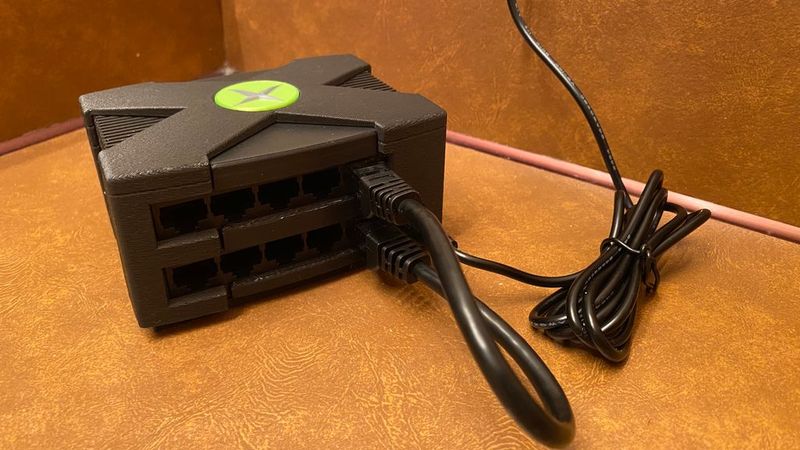
Assembly Steps - with the InnerShell upside down on its top, insert the first LED light Diffuser into the first row slots, it should click in firmly. Then, take your first board and lower it down into the shell, lining up its ethernet ports and power connector with the first row of slots, the PCB holes should 'click' down onto the raised pegs in the shell. Next, place the riser with the longside of the pegs facing up towards you, it should also 'click' or seat onto the PCB holes, now screw in a long M3 screw (7/8" or longer) it will be a bit tough since it's self tapping into the plastic, make sure to 'pinch' components together to get a tight fit as screw works through shell and riser pegs. Next, repeat the first few steps for the second LED diffuser and switch PCB, finally dropping the BasePlate onto the assembly, it should slot into the PCB holes as well, finally taking some shorter M3 screws (3/8" should be plenty) and screw it together. The final steps are easy, simply flip the assembly right side up, then slide the OuterShell down onto it until it clicks and locks in, remembering to install it with the cutouts on the back for the ethernet and power plugs. Finally you can drop your center gem of choice into the circular insert on the OuterShell, I designed it to just sit loosely, but a drop of superglue should more than secure it if you wish.
Finally, a last tip for use, remember that even though the power is connected inside, the switches themselves are not, you will need a short ethernet jumper cable to connect a port of each row. Effectively this means you can either have two 5 port switches, or one larger 8 port switch in the enclosure.
A quick message from me:
I designed this for myself, to the degree of which I was comfortable DIY-ing these simple electronic devices. Is there probably a better or cleaner way to do this? Yes, absolutely. But I just wanted to do this neat little project for the sake of it, and if others want to attempt to make it as well, I hope they enjoy it too.