Thermal cam mount

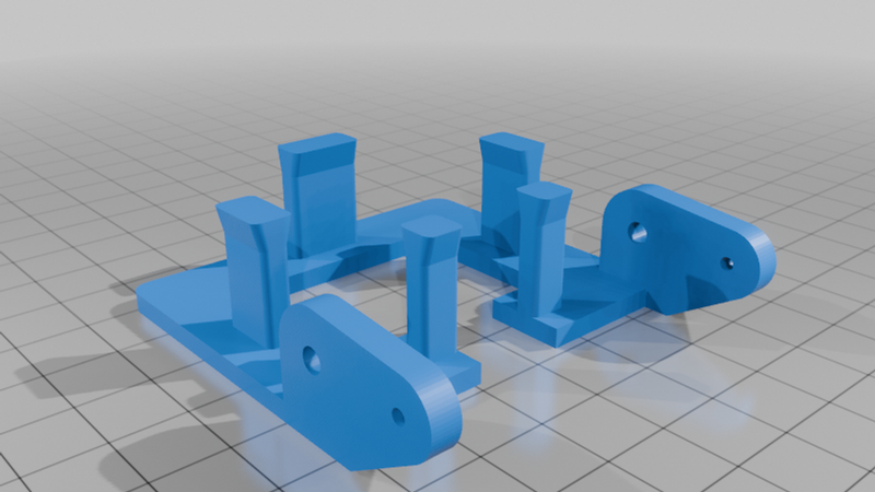
Description
Thermal cam mount
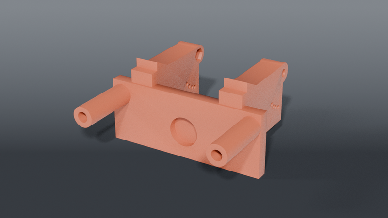
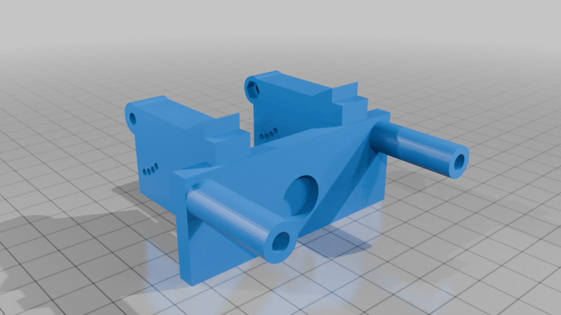
A two-part sandwich clamp on the LED-56S ring light's control-box tab (49.65 × 32.51 × 26.42),
carrying an open tray that a Sipeed T256s lies flat in, looking straight down at the board
through a window.
The T256s is registered onto the scope's visible feed so a hot component's bloom labels that
component. That registration transform is computed once and has to hold between sessions — so
the mount is rigid, non-drifting, and fixed-angle. Anything that can rotate or creep invalidates
the calibration.
Parts
| File | What | Size |
|---|---|---|
| `mount_bottom.scad` | bottom plate + web + camera tray | 70.05 × 78.3 × 62.8 mm |
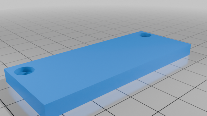
| `mount_top.scad` | top plate, counterbored | 70.05 × 28.0 × 5.0 mm |
Two M3 screws into heat-set inserts draw the plates together. Shared dimensions live in
`thermal_cam_mount_common.scad`.
Why a sandwich and not a bracket
The tab is a boss on top of the ring, which rules out five of its six faces:
| Face | Why it's unusable |
|---|---|
| Rear | merges into the ring |
| Front | brightness wheel |
| Both sides | switch and jack |
| Bottom | centre screw |
| Top | clear — the only one |
So the plates grip the top and bottom faces over the front 28 mm of the tab's 32.51, and the two
screws pass outboard of the tab at the front corners — clear of the mid-side controls, either
side of the front wheel. No rear wall, no side walls.
The long top-and-bottom grip is the moment arm that resists the camera's weight tilting the whole
thing nose-down. The bottom plate carries a pocket for the tab's centre screw.
Tab measured 2026-07-23: 49.65 W × 32.51 front-to-back × 26.42 thick.
The camera lies flat in a tray
Modelled on the reference design the user supplied (Thermal Camera Mount type 3 v3.2): open tray,
round lens window, corner posts, shallow tilt. That reference glues to the ring; this clamps the
control-box tab instead, which is the half that already worked.
This is what fixes the cable. The old cradle stood the camera upright and tilted it 60°, which
aimed its top edge — where the male plug and the live cable are — at (0, −0.87, +0.50): up and
inward, straight at the objective. The cord crossed in front of the scope and made it unusable.
Lying flat, the plug edge points sideways, and which sideways is a free choice. It's set
outboard, away from the optical axis, and the tray's outboard border is notched so the plug and
lead drop clear.
| | |
|---|---|
| Tray tilt | 14° — the reference's 14.1°, rounded |
| Lens window | 34 × 26 rounded rect |
| Retention pads | 5, at the middle of each edge — 2 × 10 mm long sides, 12 mm outboard, 2 × 6 mm inboard |
| Pocket clearance | 0.2 mm total, ~0.1 per side |
| Plug notch | 14 mm, inboard border — the high side of the tilt |
Print the coupon first
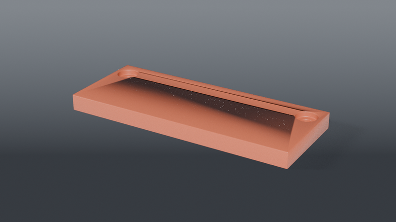
`coupons/cam_fit_coupon.scad` is the tray alone — flat on the bed, no arm, no clamp plates. ~8 g
against 14 g and four hours for the real mount. Drop the camera in: it should take light thumb
pressure to seat and stay put when the coupon is turned upside down. Two full mounts have already
been thrown away for a fit that a coupon would have caught in twenty minutes.
⚠️ The arm is ONE web. Do not split it. It was briefly two legs straddling the plug notch,
on the belief that the notch would otherwise cut it in half. The notch is subtracted inside
`_tray()`, before the arm is unioned — it never touched the arm. The split cost 44% of the section
(365.6 → 205.6 mm²) and left two 10.3 mm posts with 16 mm of support packed between them for the
arm's whole height; prying it out snapped them off the bottom plate. 2 h 45 min and 45 g.
`check_arm_clearance.py` now proves the arm stays out of the camera pocket, so there is no reason
to reach for a split again.
⚠️ The coupon does not cover the arm. `coupons/cam_fit_coupon.scad` is the tray alone. It
validates the pocket and is structurally blind to everything that carries load. A passing coupon is
not evidence the mount will survive support removal.
⚠️ The plug exits on the INBOARD edge, and that is deliberate. The tray tilts 14° down toward
+Y, so the inboard edge is the high one and a plug leaving it points up-slope. That is what keeps
the device's screen visible and its touchscreen reachable while the camera is being placed. The
first build had the notch outboard, on the low side, which buried the plug under the mount. The arm
is split into two legs straddling the notch for the same reason — a single centred web sat exactly
where the relief has to go.
⚠️ The pads are not at the corners, and that is the whole point. The first printed tray
fenced the pocket with four 4 mm posts standing at its corners. The camera slid around freely
inside it, because the body's corners are radiused — a post in a corner touches nothing but air.
Contact has to land on the flat middle of a side, the one part of the outline whose position does
not depend on a corner radius nobody has measured. Anything that moves a pad back toward a corner
reintroduces the failure.
⚠️ The window is deliberately oversize. The notes record the thermal lens as "offset toward
LEFT" and that offset has never been measured. A window cut to a guessed centre would blind the
camera, and no mesh check catches a part that's the right shape over the wrong spot. 34 × 26 in a
42 × 35 body leaves a 4 mm border all round and clears the optic wherever it sits.
The tray hangs BELOW the clamp
The control housing sits behind the lights and the space under it is clear. An earlier version
of this file claimed "everything below the tab is the working volume" and pushed the camera up on
top of the clamp. That claim was wrong and it is what put the camera in the worse place.
Below is better: it drops the camera about 34 mm, much closer to the objective's plane, which
cuts the parallax the HUD registration has to correct — the whole reason the mount exists.
The pre-2026-08-08 version that hung below failed because of an inverted tilt sign that aimed
the lens up into the objective. That was a real bug, and the position got blamed for it. A flat
tray looking down through a window cannot repeat it.
`mount_bottom` now carries the web and tray; `mount_top` is a plain counterbored plate.
Why the tray reaches 26 mm out
`ARM_FWD` is 26, not the old cradle's 19.5. At 19.5 the bottom clamp plate clipped the innermost
3.8 mm of the lens window about 35 mm down — the camera couldn't see the part of the board nearest
the objective, which is the only part worth seeing.
Swept against the real sight line: blocked at 19.5 and 22, clear from 24. 26 leaves 2 mm of margin.
Flattening the tilt to 8° also clears it, but that aims the lens nearer straight down and gives up
inward coverage. Reaching further out costs 6.5 mm of offset against a 175 mm field — nothing.
The arm is a plain web, and that took five tries
Every attempt to `hull()` onto the tilted tray produced a different degeneracy on OpenSCAD 2021.01:
| Attempt | Result |
|---|---|
| Square patch, tray-sized | corners proud of the rounded outline — 4 non-manifold edges |
| Patch matching the outline exactly | hull arrives tangent to the tray's side walls — 10 edges |
| Patch butted on the tray's underside | three faces on one line — 2 edges |
| Patch pushed inside the tray | zero-length edge |
| Hull of two solid blocks | 4 edges |
Bisection put it on the arm-to-tray join every time — tray alone passed, arm alone passed, together
they failed, with or without the pads and the window.
A plain box has flat faces. Where it meets the tilted tray, two planes cross at 14° — an honest
intersection with nothing coincident, coplanar or tangent. It passes.
The cradle rides above the plate, not below
The tab is coplanar with the ring light's disc, so everything below it is the working volume
between the objective and the board. The camera must never enter it.
An earlier version hung the cradle below the bottom plate, rotated `-(90 - CAM_ANGLE)`. That put
the camera in the working volume and aimed the lens 60° up into the objective — two failures at
once. Fixed 2026-08-08: the cradle sits above the top plate, just outboard of the tab's front
face, sighting down past the plate's front-top corner.
`verify_aim.py` exists so that can't regress silently. It checks the lens vector and the corner
clearance:
```sh
python3 verify_aim.py
```
```
lens vector dY=-0.500 dZ=-0.866 -> 30.0 deg from vertical, INWARD, DOWN
ray 9.0 deg clearance +1.30 ok
lowest cradle point z=18.36 (top plate underside z=13.36) -> out of the working volume
PASS
```
Run it before any print. A mount that aims the lens at the objective still renders, still
slices, and still passes a mesh check.
Still to confirm on the first print
- `FIT = 0.3` — the gap between each plate and the tab face. Too loose and the calibration
drifts, which is the one thing this mount exists to prevent.
- Front-corner screw clearance — that the screws really do pass outboard of the wheel.
- That the tab's top face is rigid ABS before trusting the grip.
Recommended print settings
| | |
|---|---|
| Material | PETG or ABS — not PLA, it creeps under clamp load |
| Layer height | 0.2 mm |
| Walls | 4 perimeters |
| Infill | 40 % — this is a clamp |
| Supports | `mount_top`: YES. `mount_bottom`: none. See below |
Supports — mount_top only
Measured off the exported mesh, not eyeballed:
| Part | Surface that is unsupported overhang steeper than 45° |
|---|---|
| `mount_top` | 14.3% |
| `mount_bottom` | 0.0% |
`mount_top` carries two ~470 mm² faces that are flat-down — 0.1° off horizontal, hanging in
air — plus the cradle's 30° faces, because the cradle is tilted 60° from vertical by design. That
is not a marginal overhang; it is a ceiling.
This README said "Supports: none" for both parts until 2026-08-27, and a print was started on
that basis and killed. `mount_bottom` genuinely needs none — it is a plate with a pocket.
Set supports per-object. If both parts share a plate, a global support setting grows them
under `mount_bottom` for nothing.
The tilt is adjustable — set it on the bench, lock it with a pin
`TRAY_TILT` was a fixed 14° for months, inherited as "the reference's 14.1, rounded" from a
downloaded model and never checked against this scope. The lens sits ~43 mm outboard of the optical
axis; at 14° the axes don't meet until 172 mm down, so the thermal view landed 2–3 cm off the field
at real working distances. Twenty-odd reprints went into guessing a fixed number.
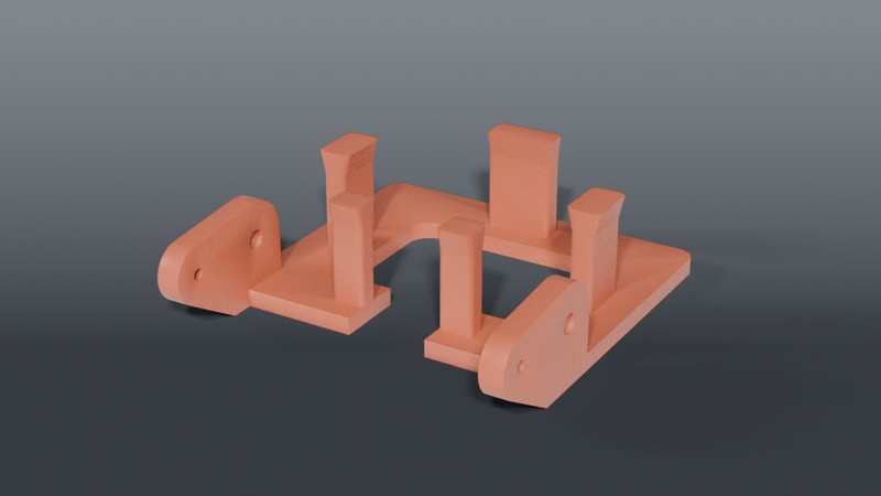
`mount_tray` pivots on the arm's legs and locks at 10° steps, 15–45°. Two M3s (one per side,
into nut traps on the legs' inner faces) are the pivot. A 1.75 mm filament stub through the
yoke's index hole and one of the four on each leg is the lock. It cannot creep. Set by eye against
the app, pin it, done.
| hole | tilt | axes cross | typical use |
|---|---|---|---|
| 1 | 15° | 142 mm below the lens | far working distance |
| 2 | 25° | 76 mm | start here |
| 3 | 35° | 46 mm | close work |
| 4 | 45° | 28 mm | very close |
`verify_aim.py` prints the full off-axis table per hole across 50–130 mm. A 10° step is ±10 mm at
the work plane — the app's overlay absorbs that; it cannot absorb the 20–30 mm the fixed tilt gave.
What the first adjustable version got wrong — all of it printed
| defect | how big | how it got through |
|---|---|---|
| the two parts overlapped | 2,330 mm³ | no part-vs-part check existed |
| the yoke sat inside the camera pocket | 1,021 mm³ | pivot placed at the pocket's edge |
| 15.5 mm of yoke hung below the tray floor | — | never checked the part's own z-min |
| the legs entered the camera | 320 mm³ | pivot on the camera's face |
| three of four index holes were in thin air | — | pin check passed through empty space |
`check_assembly.py` now exists and catches every one of those. It intersects the two parts at every
index step (must be empty), the tray and legs against the camera's seated volume (empty), the index
pin against both parts (empty — unblocked) and a probe around the pin against both parts (must be
~450 mm³ — material, not air). It was negative-tested against the shipped geometry and fails on it.
Every checker in this directory now renders the assembled geometry and reads its constants out of
the `.scad`; three of them had their own copies and passed on empty space after the split.
Why a filament pin
Serrations need a full 360° ring, which never fit on a 10 mm bar. M3 index holes 5° apart need a
50 mm radius just to stop merging into a slot. A 1.75 mm stub through 2.0 mm holes on a 30° arc at
r 15 fits on the plain bar, prints trivially, and can't creep.
| part | | orientation | support |
|---|---|---|---|
| `mount_bottom` | plate + bosses + legs, ~40 g | front-down as emitted | grid, not tree |
| `mount_tray` | tray + yoke paddles, ~15 g | floor down as emitted — 2070 mm² on the bed | none (24 mm² of lip underside, self-supporting at 37°) |
| `mount_top` | unchanged | — | — |
| `coupons/joint_coupon` | one leg end + one yoke, ~9 g | flat as emitted | none |
Print the joint coupon first. It is the only untested mechanism: does the M3 seat in the nut
trap, and does the pin drop through yoke and leg at each of the four holes? Nine grams answers that
before 55. All four index holes are verified present in its cross-section.
`verify_aim.py` reads the model, on purpose
It used to carry its own copies of the constants, and they drifted badly: it modelled a 60° upright
cradle with `ARM_FWD` 19.5 and the pre-caliper camera long after the design became a 14° flat
tray at `ARM_FWD` 26. It reported PASS throughout, including in two release notes.
It now parses `thermal_cam_mount_common.scad` and exits with an error if a constant it needs has
gone. Do not reintroduce literals into it — a checker with its own copy of the numbers is one
that will eventually validate a part that does not exist.
It checks that the lens points down and inward at every index hole, reports the off-axis error per
hole across 50–130 mm, and that the view cone clears the window without the floor vignetting it. Negative-tested: flipping the tilt
sign and shrinking the window both make it fail.
Parametric OpenSCAD source, render scripts and every revision: https://github.com/IamMrCupp/3d-printer-models/tree/main/thermal-cam-mount
These files are release thermal-cam-mount/v3.0.0 — rendered from source and mesh-validated in CI. Newer versions, if any: https://github.com/IamMrCupp/3d-printer-models/releases?q=thermal-cam-mount