Tray for PISugar3+ and Raspberry PI
Description
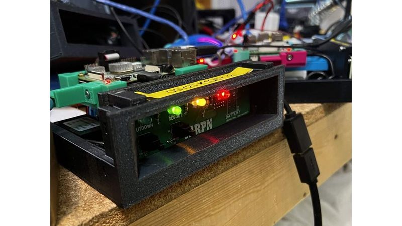
This tray is designed for the TARPN project, to hold the computer elements for a packet radio node.
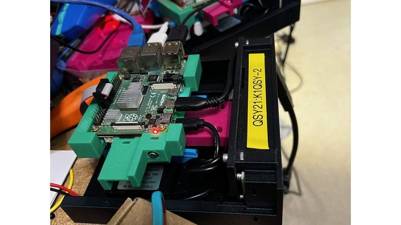
The tray holds a 12V to 5V regulator, PiSugar3+, Raspberry PI 3, 4 or 5, and a TARPN Control Panel.
Parts:
(1) assembled TARPN 4-LED control panel PCB
(1) 2x5 pin IDC to IDC 10-conductor ribbon cable as described in the control panel assembly.
(1) Raspberry PI 4B
(1) Pi Sugar 3 plus (DO NOT TOUCH the spring loaded contactors)
(4) M2.5 14mm long screws with nuts,
(4) M2.5 nuts (smallest you can find to fit in the screw keep-out on Raspberry PI),
(15) M3 square nuts mcmaster.com https://www.mcmaster.com/products/97259a101/
(15) M3 screws 10mm long.
(2) Ty-raps -- I used 3.6mm wide x 8" wraps
Assembly instructions:
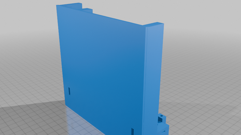
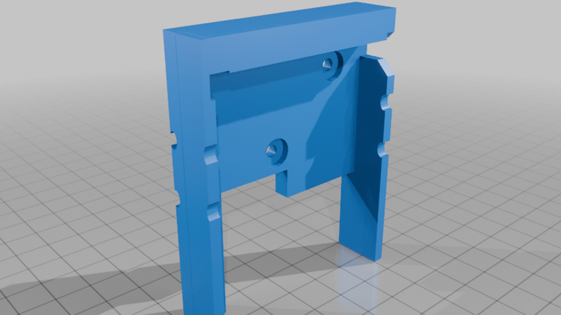
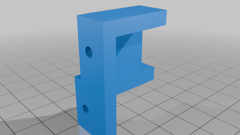
Assemble the control panel PCB onto the main box structure using the back-of-the-front-panel piece using 6 M3 sscrews and square nuts.
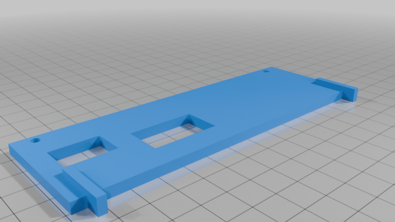
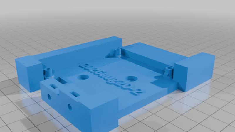
Attach the Raspberry PI mount plate to the top side of the 'stub'.
Using M2.5 bolts, screw the PISugar3+ onto the Raspberry PI mount so the battery connector clears the board. The battery connector is toward the outside left of the assembly from the perspective of the front of the front panel.
Using M2.5 nuts, screw the Raspberry PI onto the ends of the screws coming through the PiSugar3+ board.
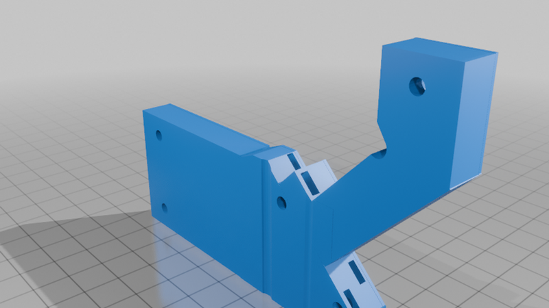
Attach the battery mount to the stub using two M3 square nuts and screws. The battery mount's arms face toward the 'front' of the stub where the two screw holes will later be used to screw the stub into the main box structure.
Place the battery into the mount such that the output wire may be plugged into the PiSugar. Secure the battery using the two ty-raps.
Slide 3 nuts into the rear portion of the main box structure, and screw the 'stub' into the main box structure.
Attach ribbon cable between the PI and the control panel as described in the control panel instructions.