Adjustable Ball-Joint Wall Mount for Reolink Lumus
Description
To Do:
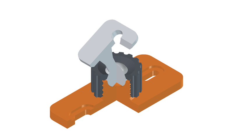
Split ball joint so it can be assembled
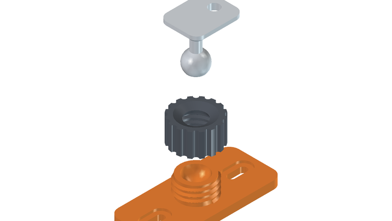
A three-part wall mount that replaces the fixed bracket on the Reolink Lumus with a proper ball joint, so you can aim the camera freely after it is mounted.
What it does
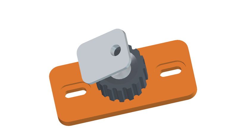
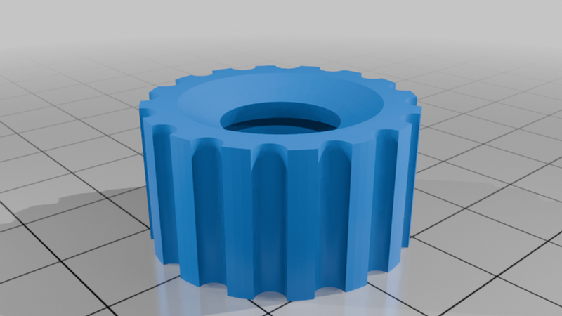
The camera plate sits on a ball joint that gives ±36° of tilt in every direction plus unlimited rotation about its own axis. Aim it by hand, then lock it by hand-tightening the knurled ring. No tools needed for adjustment.
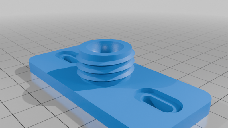
The wall plate uses two vertical screws 52 mm apart. Both holes are 4.5 × 12 mm slots, so you get around 7 mm of height adjustment after the holes are drilled, on top of what the ball joint gives you.
Mounting the camera
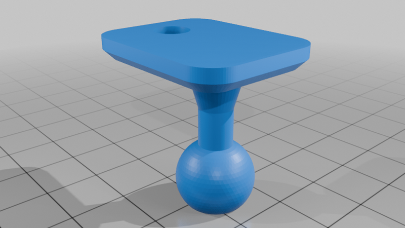
The camera plate is 4.00 mm thick with a 6.5 mm through hole, matching the original Lumus mounting tab exactly, so the M6 screw that came with your camera works without modification. The plate measures 24 × 30 mm, considerably larger than the stock contact area, so the camera foot is fully supported. There is clear access behind the hole for the screw head and a hex key.
How it works
The ball is held between a spherical seat in the wall part and a conical clamping face in the ring. The cone contacts the ball at its equator, where the friction radius is largest. Tightening is progressive — 0.2 mm of travel is enough to take up and start clamping — and the ring's narrowest opening is smaller than the ball, so it cannot fall out once the ring is on.
The thread is M22 × 3.0 with 0.25 mm radial clearance on both crest and root. It should run smoothly on a well-calibrated printer. If it feels stiff on the first assembly, just run the ring back and forth a few turns to bed it in.
Printing
Three separate parts, all pre-oriented with their flat face on the bed.
The wall part and the clamping ring need no supports at all. The ball arm has a 10.55 mm flat on the underside of the ball to give it a stable footing, and every overhang from there up stays within 45°. The camera plate at the top does need support underneath — those marks land on the hidden back face.
Layer height 0.2 mm
4 walls, 25% infill
PETG recommended for outdoor use; PLA is fine indoors
No supports except under the camera plate on the ball arm
Total print time roughly 2 hours, about 30 g of filament
Consider a couple of extra perimeters on the ball arm — its 6 mm neck is loaded across the layer lines.
Assembly
Drop the ball into the seat, thread the ring on over it, and screw the wall plate to the wall. Mount the camera with its original M6 screw, aim it, and tighten the ring.
Hardware needed
Two wall screws up to 4.5 mm, plus the M6 screw supplied with the camera.