Anycubic ACE Pro Hall Sensor Board Guard – OUTPUT_V0.4
Description
Summary
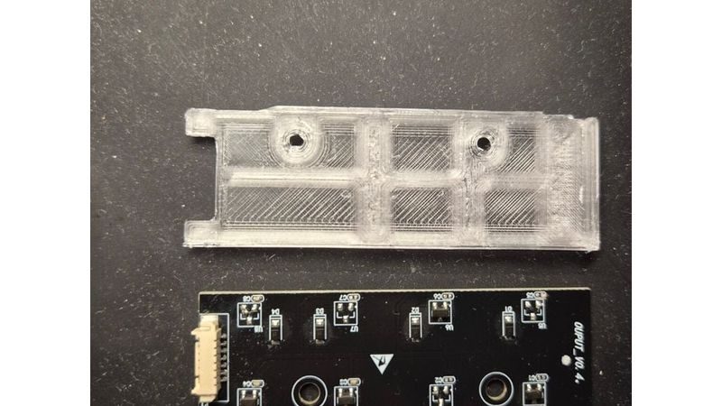
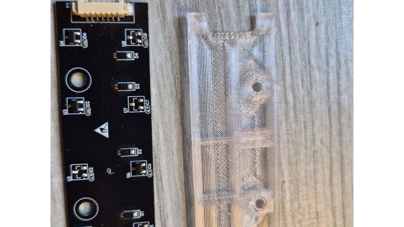
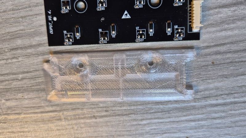
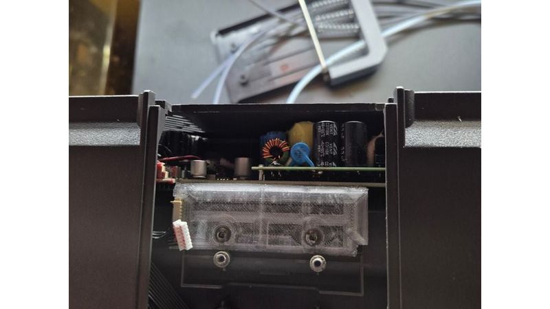
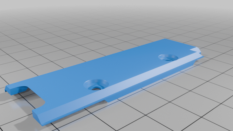
A thin 3D printed protective guard for the Hall sensor PCB inside the Anycubic ACE Pro filament buffer.
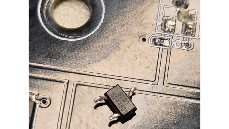
The original buffer mechanism can move with some lateral play, and in my ACE Pro this resulted in multiple Hall sensors and nearby SMD components being physically knocked off the PCB. This guard creates a mechanical barrier between the moving buffer parts and the exposed electronics while keeping the buffer movement free.
Designed for the ACE Pro OUTPUT_V0.4 Hall sensor board.
STL and editable STEP/STP files are included.
Description
I designed this part after tracking down persistent filament/buffer errors in my Anycubic ACE Pro.
The cause turned out to be mechanical rather than software-related: several Hall sensors on the OUTPUT_V0.4 sensor board had been physically torn off the PCB.
There are eight Hall sensors on this board, two for each filament buffer channel. The moving buffer sliders contain magnets and travel directly in front of these sensors. Because the plastic buffer parts have some side-to-side play and relatively sharp edges, a misalignment or jam can allow the moving part to contact the exposed SMD components.
In my unit this damaged multiple Hall sensors and some of the tiny nearby capacitors.
This guard was designed to prevent that from happening again.
The design went through approximately five physical iterations to get the tolerances right. The final version:
fits over the original Hall sensor PCB
uses the existing mounting locations
leaves the electrical connector accessible
does not interfere with the four buffer sliders
protects both rows of exposed Hall sensors
protects the small SMD components around them
is very thin and lightweight
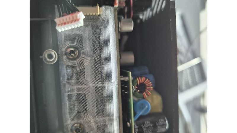
allows visual inspection of the PCB when printed in transparent PETG
requires no permanent modification to the ACE Pro
The buffer sliders have been manually tested through their full range of movement with the guard installed and move freely without catching on the printed part.
Important testing note
The mechanical fit and buffer movement have been verified.
At the time of uploading this first revision, my original Hall sensor PCB is still damaged and I am waiting for replacement components / a replacement board.
The final electrical test of Hall sensor triggering through the installed guard is therefore still pending.
The guard is made from non-magnetic plastic and the protective layer above the sensors is less than 1 mm thick, so it should not significantly affect the magnetic field itself. However, it does slightly increase the magnet-to-sensor distance, so I will update this page after testing it with a fully working Hall board.
Installation
Disconnect the ACE Pro from power.
Open the ACE Pro housing and access the buffer Hall sensor board.
Remove the two original PCB mounting screws.
Place the guard over the Hall sensor board.
Make sure the connector and cable are not trapped.
Reinstall the original mounting screws.
Before closing the ACE Pro, manually move all four buffer sliders through their full travel.
Verify that none of the sliders catch or rub excessively against the guard.
Reassemble the ACE Pro and test all four filament channels.
Do not force the mechanism if your ACE Pro has a different PCB or mechanical revision.
Compatibility
Designed around:
Anycubic ACE Pro
Hall sensor PCB: OUTPUT_V0.4
If your board revision is different, compare the mounting holes, PCB outline and connector position before installation.
Print settings used for the prototype
My uploaded G-code was sliced in AnycubicSlicerNext 1.4.1.2 with:
Material: PETG
Nozzle: 0.4 mm
Layer height: 0.13 mm
First layer: 0.20 mm
Nozzle temperature: 230 °C
Bed temperature: 75 °C
Walls/perimeters: 7
Infill: 30%
Infill pattern: Tri-Hexagon
Top layers: 5
Bottom layers: 3
Automatic normal supports enabled
Support threshold: 50°
Finished height: approximately 3.48 mm
Estimated normal print time: approximately 21 minutes
These settings are not mandatory. The model is small and can be printed with normal PETG settings appropriate for your printer.
Transparent PETG is useful because the PCB and components remain visible after installation, but any non-conductive, non-magnetic filament should work.
Included files
AceHallBoard_Guard.stl – ready for slicing
AceHallBoard_Guard.stp – editable CAD model
The STEP file is included intentionally so the community can modify the design for different tolerances or future ACE Pro hardware revisions.
Why I made this
A replacement Hall sensor board is inexpensive compared with the ACE Pro itself, but this failure appears to be preventable with a very small mechanical guard.
If your ACE Pro is producing unexplained buffer, filament feeding, tangling or sensor errors, it may be worth inspecting this PCB and checking whether all eight Hall sensors are still physically present.
If you improve or adapt this design, please share your remix so other ACE Pro owners can benefit from it.