3D Printed Case for PD140W Multi Protocol Fast Charging Module (DC 5.5x2.1mm)
Description
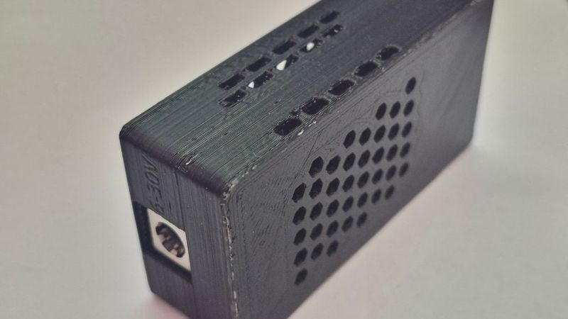
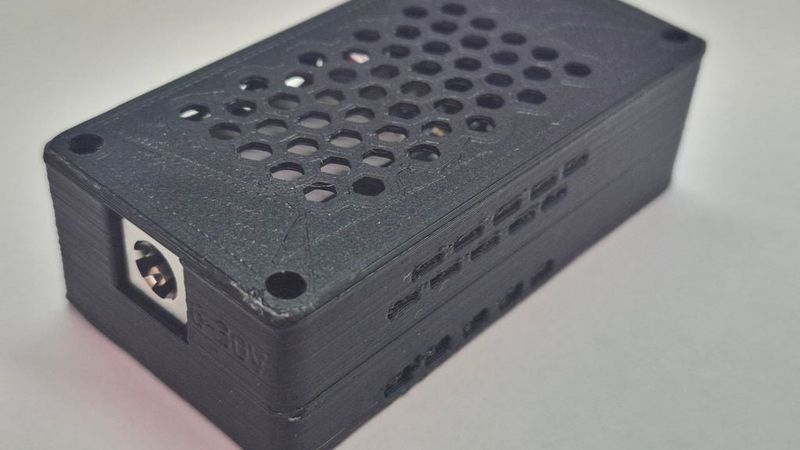
A compact, highly-ventilated 3D-printable protective case designed specifically for the popular Power Delivery (PD) fast charging step-down module sold on AliExpress (supports protocols up to PD 3.1 / 140W max output). This design provides robust physical protection for the open-circuit PCB while preserving full access to both output ports (USB Type-A + USB Type-C) and the DC barrel power input jack.
Features
* DC Input Compatibility: Designed to fit the integrated DC input jack (supports DC 9–30V input) with custom rear cutout markings for easy voltage identification.
* Optimized Thermal Dissipation:
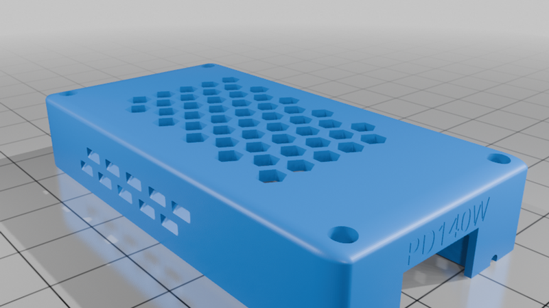
* Full hexagonal airflow mesh on the top cover to prevent heat buildup during high-power conversion.
* Side ventilation slots along both edges to promote passive convective cooling across the power inductors and capacitors.
* Secure Fit & Assembly:
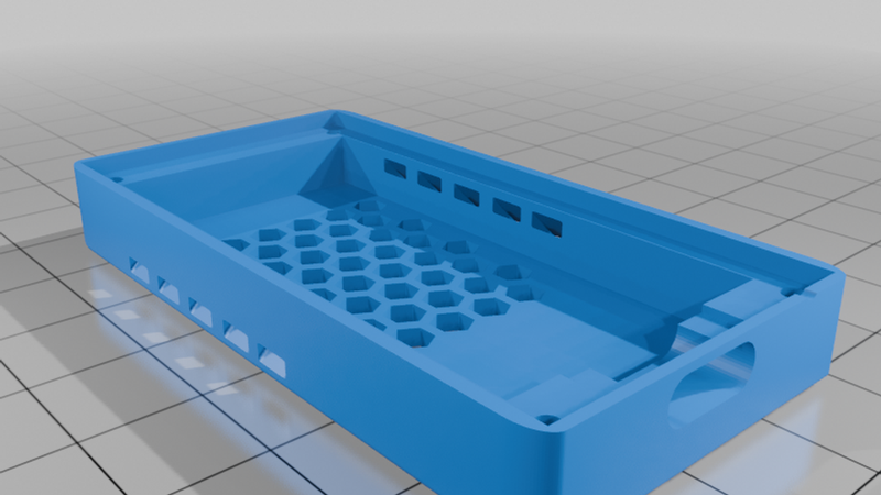
* Two-Part Enclosure: Clean snap/screw assembly consisting of a bottom housing and a top cover.
* Internal Retention: Molded alignment posts keep the PCB firmly seated during repeated cable insertions and removals.
* Standard Fasteners: Assembles securely using four M2 screws or similar self-tapping screws.
Print Settings
| Setting | Value |
| :--- | :--- |
| Printer Brand | Any |
| Printer Model | Any FDM Printer |
| Rafts | No |
| Supports | No (Designed to print clean without supports) |
| Layer Height | 0.2 mm |
| Infill | 15% – 20% (Grid, or Triangles) |
| Filament Material | PETG or ABS/ASA recommended (PLA acceptable for light loads) |
Note on Material: PETG or ABS/ASA is recommended if operating the module continuously near high loads due to heat generated by the buck-boost conversion circuit.
Hardware Required
* 1x AliExpress PD 140W Fast Charger Module Board (Dual Port: USB Type-C + USB-A)
* 4x M2 Screws (Length: 6 mm to 10 mm self-tapping or machine screws)
Assembly Instructions
1. Slide the charger PCB into the bottom housing, aligning the rear DC barrel jack into its dedicated cutout.
2. Press the board down gently onto the internal alignment corner posts until seated flat.
3. Place the top cover onto the base, ensuring the front USB-A and Type-C cutouts line up cleanly with the output connectors.
4. Secure the top cover using four M2 screws in the corner mounting holes. Do not overtighten.
Files Included
* `PD140Wcase2t.stl` – Top ventilation cover
* `PD140Wcase2b.stl` – Bottom enclosure base