Servo from DC motor



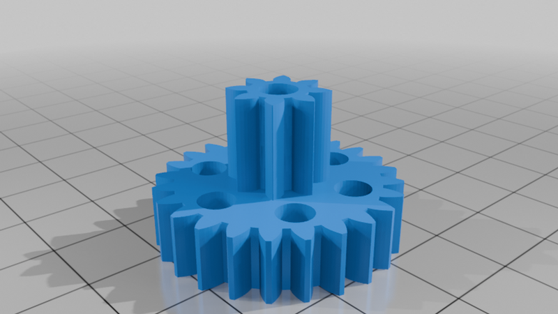
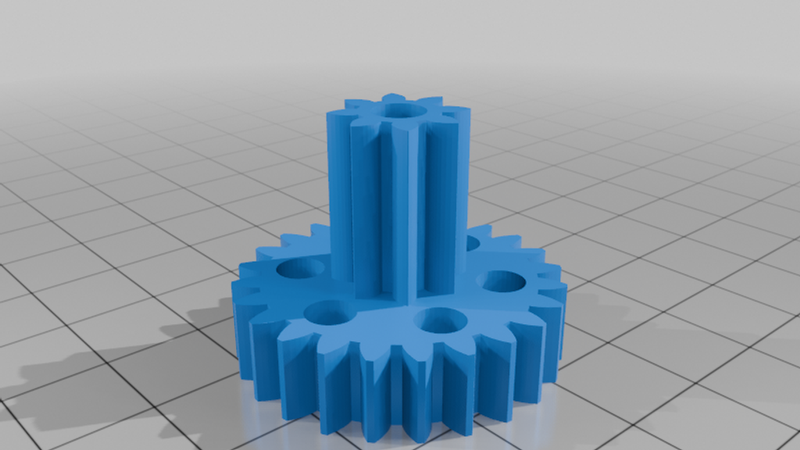
Description
3-Turn High-Torque Servo Mechanism (27:1 Reduction)
This project allows you to build a custom, high-torque 3-turn servo mechanism using a standard DC motor, a potentiometer for positional feedback, and a gear reduction system.
By utilizing a Raspberry Pi Pico and an L298N motor driver, you can achieve precise, multi-turn control for robotics, camera pans, or specialized automation tasks.
🛠 Features
* Multi-Turn Operation: Designed for 3 full rotations (approx. 1080°).
* High Torque: 27:1 gear reduction provides significant output strength.
* Feedback Controlled: The design incorporates a 1:3 gear ratio for the potentiometer, allowing a standard single-turn potentiometer to track the full 3-turn range of the output shaft.
* Open Hardware: Fully 3D printable components.
📋 Bill of Materials (BOM)
Electronics
* Controller: Raspberry Pi Pico
* Motor Driver: L298N Motor Driver Module
* Feedback: Standard Single-Turn Rotary Potentiometer
* Motor: 12V/6V DC Motor (standard brushed)
* Power Supply: Appropriate voltage supply for your motor and logic (e.g., 9V or 12V battery pack)
* Misc: Jumper wires, breadboard/prototyping board, 3D printed chassis
Hardware (Mechanical)
* Shafts: 5mm diameter brass shafts
* Fasteners - Long: 55mm long M3 bolts (for assembly and structural mounting)
* Fasteners - Short: (4) 10mm long, 3mm diameter bolts
* Nuts/Washers: M3 nuts and washers as required by the print design
3D Printed Parts
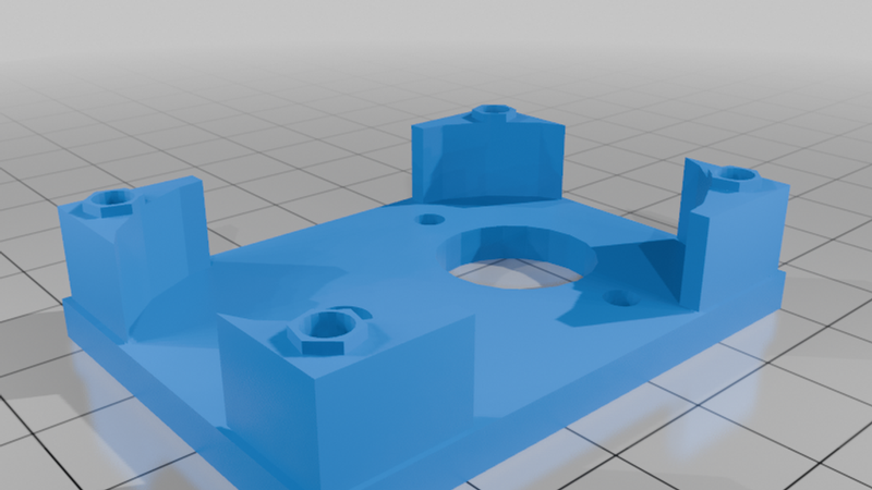
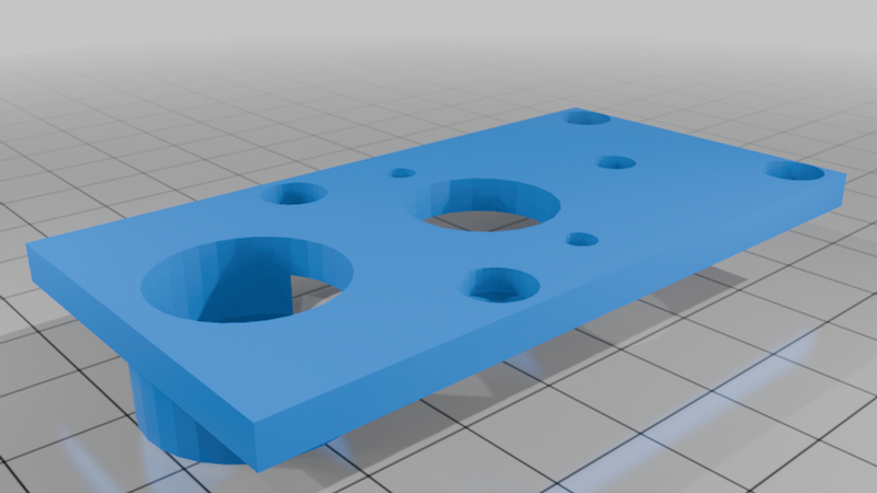
Servo Housing*
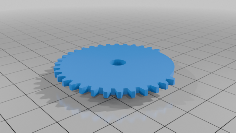
Output Gear (Main - 27:1)*
Potentiometer Gear (1:3 ratio linked to output)*
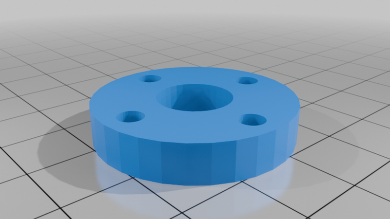
Motor Mount*
⚙️ Assembly Instructions
1. Print Parts: Ensure all gears are printed with high infill (40%+) for durability.
2. Prepare Shafts: Cut your 5mm brass shafts to the lengths specified in the assembly guide and ensure they are deburred for smooth rotation.
3. Assemble Gearbox: * Use the 55mm M3 bolts to secure the primary housing assembly.
* Use the (4) 10mm M3 bolts to mount the motor or secure the enclosure plates as specified by the CAD design.
* Install the 5mm brass shafts through the printed housings and gears.
4. Install Feedback: The potentiometer is connected to the output via a 1:3 gear set. This ensures that when the main shaft rotates 3 full turns, the potentiometer shaft rotates exactly 1 turn.
5. Wiring:
* Connect the L298N to the Pico (PWM pins for speed, Digital pins for direction).
* Connect the Potentiometer center pin to a Pico ADC pin for positional feedback.
* Connect the DC Motor to the L298N output terminals.
💻 Software & Logic
To control this as a servo, you need to implement a simple PID (Proportional-Integral-Derivative) control loop in MicroPython or C/C++.
1. Read the current position via ADC from the potentiometer (0-65535).
2. Calculate the error (Desired Position - Current Position).
3. Drive the motor forward or backward via the L298N based on the error magnitude and sign.
⚠️ Notes
* Calibration: Because of the 1:3 ratio, ensure your gear mesh between the output and potentiometer is tight to prevent backlash.
* Mechanical Limits: Ensure the main shaft has physical hard stops if your application requires them.