Noctua NF-A14 Wall Air-Vent Fan Mount (Pi PWM)
Description
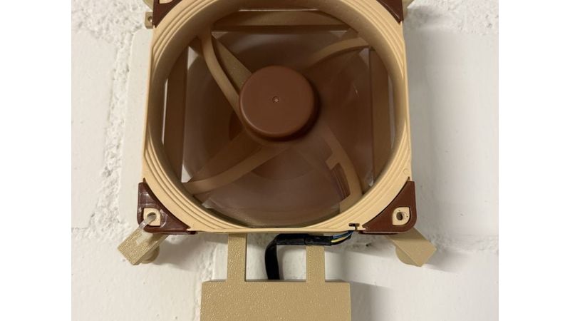
A one-piece spider that holds a Noctua NF-A14 in front of a wall air vent and pushes the vent's airflow further into the room, with an integrated Pi Zero bay for PWM speed control.
What it is
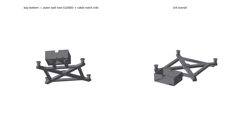
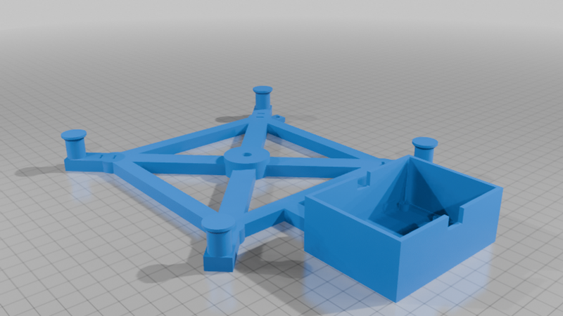
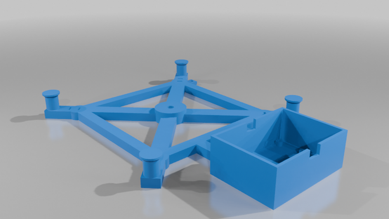
A one-piece "spider" that mounts a Noctua NF-A14 (140×140×25) coaxially in front of a wall air vent whose valve plate (Ø130) has been removed. It fits a standard Swiss wall vent (disc/plate valve): a 7 cm M6 screw (M6×70) threads into the vent's spindle; four legs land on the wall outboard of the vent and the screw tension clamps them down. The fan draws the vent's outflow and pushes it further into the room. An integrated bay on the underside holds a Raspberry Pi Zero (plus WAGO connectors and a buck converter) that drives the fan's 4-pin PWM line.
Why this one
- No wall drilling. It reuses the vent's own valve-plate screw and spindle — the wide four-leg footprint (Ø~226) carries the fan's overhang load, so the single screw isn't taking the bending force. Remove the valve plate, one screw, done.
- One-piece, support-free print. Flat spider on the bed, legs up; the countersink and nut-pocket ceilings bridge, so no supports.
- PWM speed control built in. The Pi bay recesses a Pi Zero below the rim, in the fan's airstream and hidden behind the fan. Drive GPIO18 at 25 kHz; expose fan speed to Home Assistant over MQTT.
- Fan attaches with zip ties. Each corner has a pair of slots — no fan screws needed.
How to print
- Material: ASA (room-visible, UV/heat-stable near a vent); PLA or PETG also work.
- Orientation: as modelled (front face on bed, legs up) — no supports.
- 4 walls / 20% infill, 5 mm brim (wide thin footprint; ASA warp control). 0.4 or 0.6 mm nozzle, 0.20–0.30 mm layer.
- ~3.3 h, ~87 g ASA (0.4 mm nozzle, 0.20 mm layer, 20% infill).
- Bbox 178 × 245 × 31 mm — fits within the 256 mm bed.
Wiring (optional, for the PWM control)
One 12 V supply up the wall → buck to 5 V for the Pi → fan runs on raw 12 V, PWM (blue) from GPIO18, common ground. All splices sit in the bay; the supply cable exits a notch in the closed bottom wall, the fan lead enters a notch on the vent side. A 5 V-only interim mode (USB to the Pi, fan on the 5 V rail ≈ 40% speed) works without the buck.
Good to know
- Sized for a standard Swiss wall vent, attached with a 7 cm M6×70 screw into the vent spindle — reuse the vent's own valve-plate screw where possible. If your vent differs, verify the spindle takes M6 and measure its thread depth first.
- Detailed wiring schematic available on request — ask in the comments. The Pi control software (PWM daemon + Home Assistant / MQTT) can be shared the same way.
- The legs sit at ±80 mm to clear a Ø130 valve-plate zone; if a wider trim ring remains on the wall, the feet may land on it.
- The Pi bay hangs below the vent in open space — check there's clearance behind where it hangs.
- The fan's intake (open rotor) faces the wall; exhaust faces the room.