SCARA ROBOT ARM using NEMA17 motors
Description
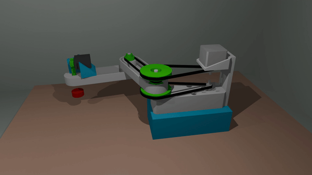
3-Axis SCARA Robot Arm (Belt-Driven)
A compact, highly responsive 3-Axis SCARA (Selective Compliance Assembly Robot Arm) robot arm designed for experimental robotics, drawing, light-duty pick-and-place, and educational purposes.
This design utilizes a robust dual-stage NEMA 17 layout for the primary SCARA joints (X/Y planar movement) and a lightweight hobby servo for the Z-axis (vertical actuation), striking a balance between torque, precision, and simplicity.
📐 Technical Specifications
* Kinematics: SCARA (Selective Compliance Assembly Robot Arm)
* Degrees of Freedom (DoF): 3 Axes
* Maximum Horizontal Reach: 163 mm
* Z-Axis Travel: ~45 mm
* Primary Actuators (Axes 1 & 2): NEMA 17 Stepper Motors
* Z-Axis Actuator (Axis 3): Standard Hobby Servo Motor
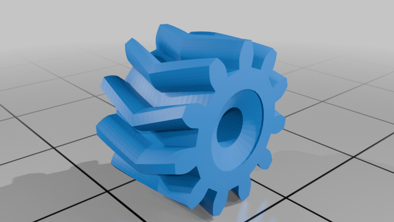
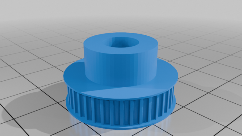
* Drive Mechanism: GT2 Timing Belts & Printable Pulleys
🔧 Design & Assembly Notes
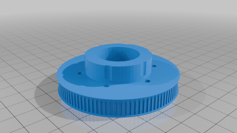
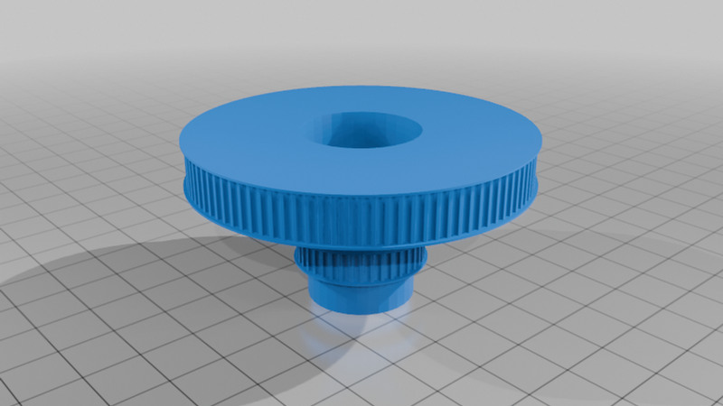
⚙️ Printable Pulleys & Smooth Rotation
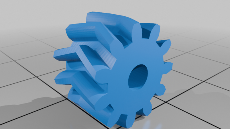
To keep hardware requirements low, the GT2 drive pulleys in this design are fully printable. For the best performance and to ensure the teeth mesh cleanly with the belt, print the pulleys using a well-calibrated machine with fine layer heights (0.12mm or 0.16mm recommended).
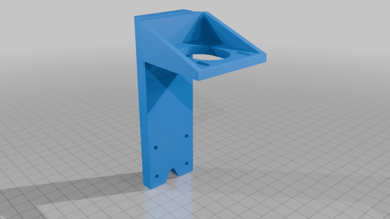
The main articulation joints rotate on standard skatewheel bearings (608 type) smooth-riding on 8mm rods/dowels to ensure low friction and minimal planar play. Note that Joint 3 (J3) uses a smaller 4mm shaft, along with a 3mm screw/bolt for its specific oddball belt idler.
🛠️ Pro-Tip for Tight 8mm Rod Fits (Drill-Reaming Method)
Depending on your printer's extrusion calibration, the printed holes for the 8mm rods might be a very tight friction fit. To achieve a perfectly concentric, zero-slop fit without cracking the plastic:
1. Chuck the 8mm metal shaft directly into a handheld drill.
2. Ensure you are aligned perfectly straight and square to the printed hole.
3. Spin the drill at moderate-to-high speed while driving the shaft slowly into the plastic.
4. The friction generates localized heat, allowing the metal shaft to perfectly "ream" and mold the plastic to its exact outer diameter. Keep the drill moving so it doesn't dwell too long and melt the wall structure, and let it cool completely once seated.
🧵 Splicing the Open GT2 Belts (Scarf Joint)
This design uses open-loop belts spliced manually into custom continuous loops to maintain a compact footprint. Do not try to 3D print the belts—they will stretch and fail. Instead, follow this overlap method to create a high-strength joint:
1. Cut the Extra Length: Calculate your required belt loop length and add an extra 3 to 5 teeth (~6–10mm) for the overlap zone.
2. Shave End 1 (The Teeth): On the first end of the belt, use a sharp razor blade or hobby knife to carefully slice the rubber teeth completely off down to the internal fiberglass cords. Do not cut through the structural cords.
3. Shave End 2 (The Backing): On the second end, flip the belt over and slice away the smooth rubber backing down to the fiberglass cords for the exact same length.
4. Test Alignment: Test-fit the two shaved sections together. They should overlap flush, keeping the standard belt thickness and perfectly maintaining the 2mm tooth pitch. Use a scrap piece of GT2 belt as a temporary jig underneath to keep the teeth perfectly aligned during assembly.
5. Glue: Clean the exposed cords with a bit of alcohol, apply a thin layer of high-strength Cyanoacrylate (Super Glue / CA Glue), press the overlapping halves together tightly, and clamp until fully cured.
⚙️ Bill of Materials (BOM) - Summary
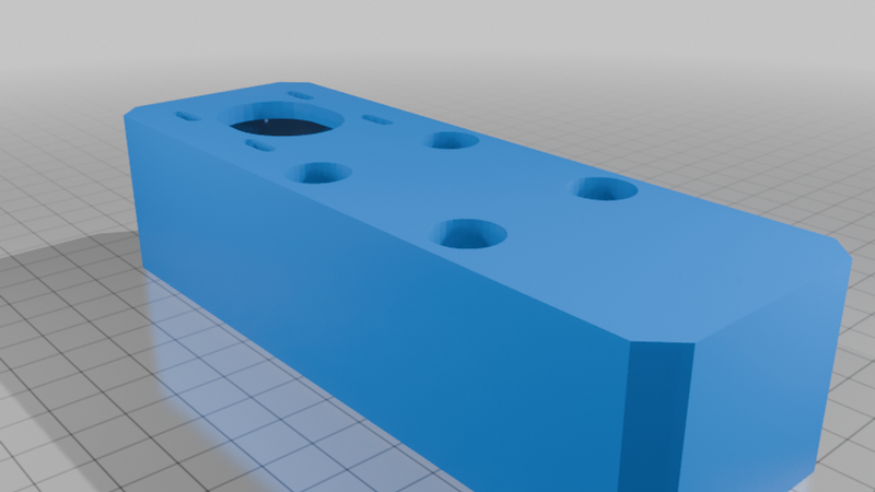
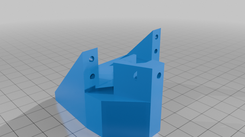
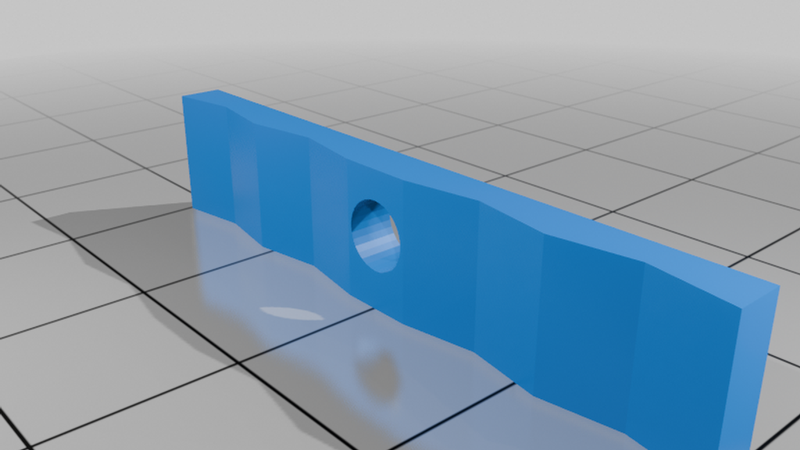
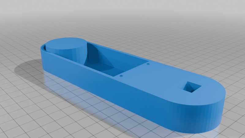
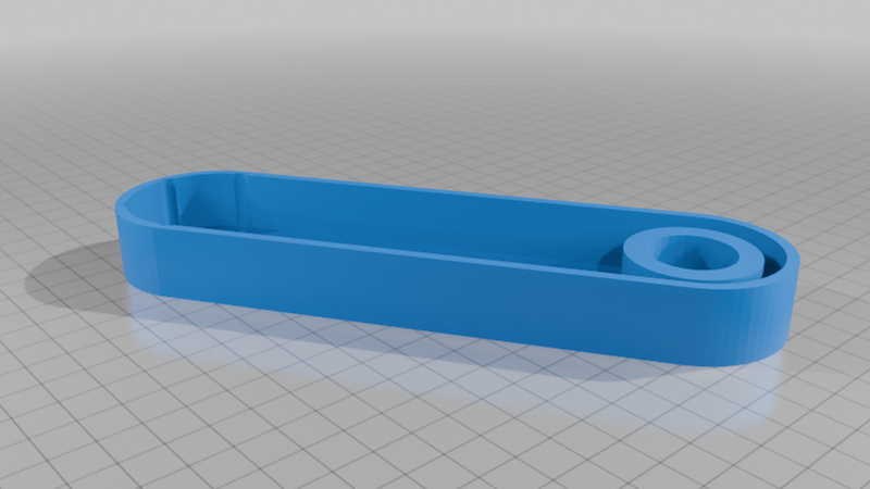
3D Printed Parts: Main arm segments, chassis structures, and Z-axis mounts (See files tab)
* Printable GT2 drive pulleys
Motors: 2x NEMA 17 Stepper Motors (for Joint 1 and Joint 2) https://www.amazon.com/dp/B0FP1TVNVJ
* 1x Hobby Servo Motor (for Z-axis lift) https://www.amazon.com/Torque-Waterproof-Steering-Digital-Control/dp/B09F9CZ89N
* Motion & Hardware:
* GT2 Open Belt (Standard fiberglass-reinforced rubber) https://www.amazon.com/dp/B08SMFM3Z6
* Standard Skatewheel Bearings (608 bearings for the primary joints) https://www.amazon.com/Bearings-Miniature-Skateboards-Electric-Scooters/dp/B0G34JLXLK
* 8mm Rods (for primary joint shafts) https://www.amazon.com/dp/B07CKZ73KN
* 4mm Rod/Shaft (for Joint 3)
* 1x M3 Screw/Bolt (for the J3 idler)
* Assorted M3 / M4 / M5 screws and nuts for frame assembly and motor mounting. https://www.amazon.com/dp/B0FGX859K
🚀 Print Settings
* Material: PLA+, PETG, or ABS (PETG/ABS recommended for structural stiffness around motor mounts and pulleys)
* Infill: 25% - 40% (Use Gyroid or Grid for structural integrity; 50%+ recommended for the printable pulleys)
* Wall Lines / Perimeters: 3 or 4 minimum
* Supports: Needed on specific overhang parts (check your slicer orientation to minimize supports)
💻 Electronics & Firmware
This arm can be driven using an Arduino with a CNC Shield (GRBL) or a dedicated 3D printer mainboard (Marlin / Klipper). https://www.amazon.com/Controller-MEGA2560-Soldered-Stepper-Drivers/dp/B08N578PRN
* Define your steps/mm based on your printed GT2 pulley tooth count and stepper microstepping settings.
* Configure the Z-axis output to send a PWM signal to control the hobby servo positioning.
If you build or remix this project, please share a Make! I'd love to see what you use it for.