18650 Battery Retainer and Holder with BMS Cavity
Description
I created this remix because I wanted to add a BMS cavity as well as a holder for the battery retainer. It's hard for me to find LR44 or any other type of button batteries where I'm at, but I have plenty of 18650 batteries. One 18650 can replace three LR44 (or other 1.5v) batteries for the majority of electronics, not only that, but they have way more amperage potential, so whatever they swap out, will run for a lot longer on one charge (and no waste, since you can recharge 18650s).
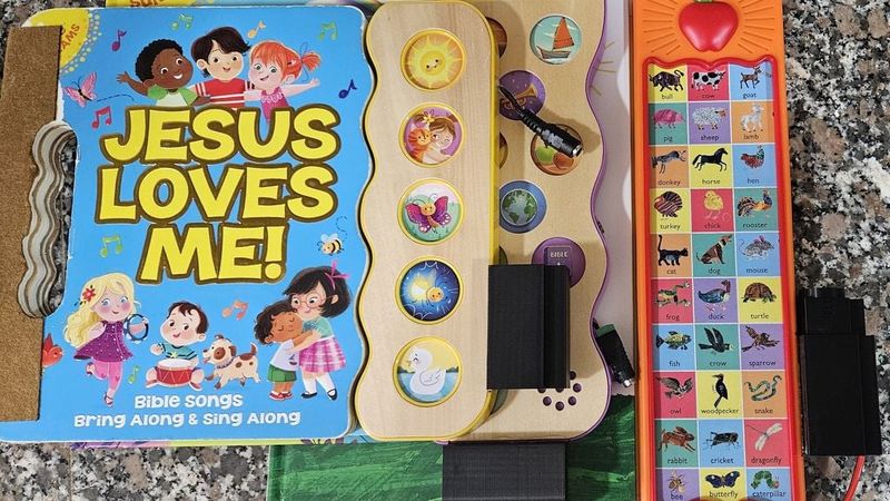
I fixed three of my kids' books with this model (and also rebound one with a felt binding, but that's another topic).
Parts Used:
DC Power Jack Set:
https://www.amazon.com/dp/B07CWQPPTW?ref_=ppx_hzsearch_conn_dt_b_fed_asin_title_12
BMS for 18650 (prevent the 18650 from going below 3A, which can ruin an 18650):
https://www.amazon.com/dp/B07W75BQWW?ref_=ppx_hzsearch_conn_dt_b_fed_asin_title_6
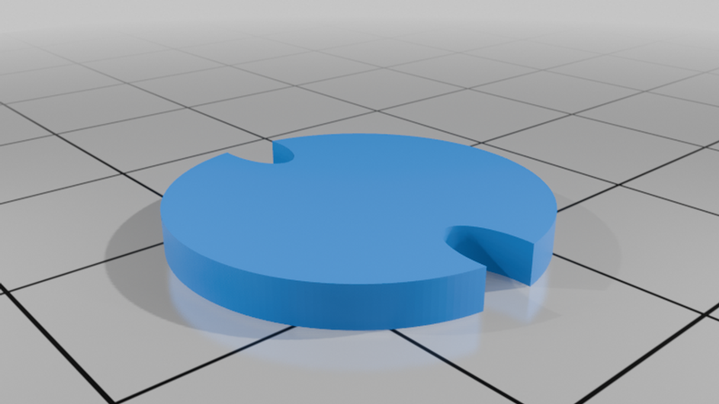
I wanted to be able to swap out the battery from within the retainer, as well as be able to swap out the retainer from one book to another. I also place a TPU spacer in the top of the retainer, below the screw plug (I cut one out of one of the flow rate calibration rectangles that I had laying around, one can easily add a simple model cylinder of a thickness of about 2mm and a diameter of 18.5mm or less). I wanted to have a little static pressure against the solder belt. I went ahead and created a spacer as I was typing this and included it, that way someone doesn't have to make their own later on.
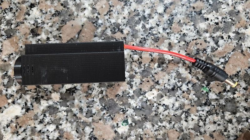
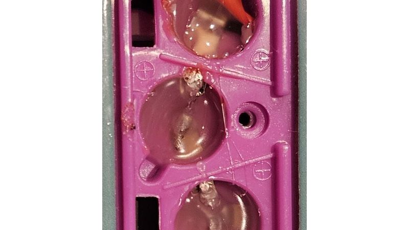
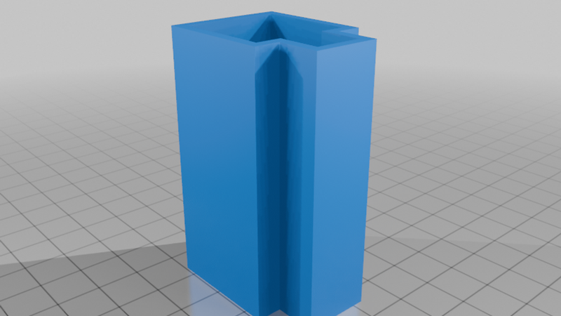
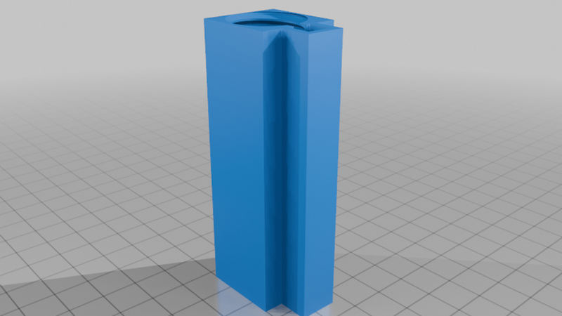
To build the battery holder thing with the BMS, run the leads through the bottom and out of the top (top is the side with the screw plug), then feed the BMS partially inside between the leads and the inner body (but on the outside of the two walls that are in there) and put a tiny angle on the bottom of the negative solder belt. Next, solder the positive and negative leads to the BMS in the proper area (center mass of the circuit board), next, feed the BMS with the wires soldered on, down the cavity. I chose to use the 18gauge pigtails to have it a little sturdier for the battery, so I made the holes large enough for that to easily slide, with a touch of tension. You will then want to take some long tweezers and move the negative solder belt to the center of the bottom, over the battery negative nub in the model. Slide the 18650 into the case, bend the positive solder belt over the top, then put the TPU retainer into there. You may want to use your tweezers to press the belt from the cavity into the main body, then push the TPU in there, that way it's tight. Last, screw on the lid of your choosing, from the original creator.
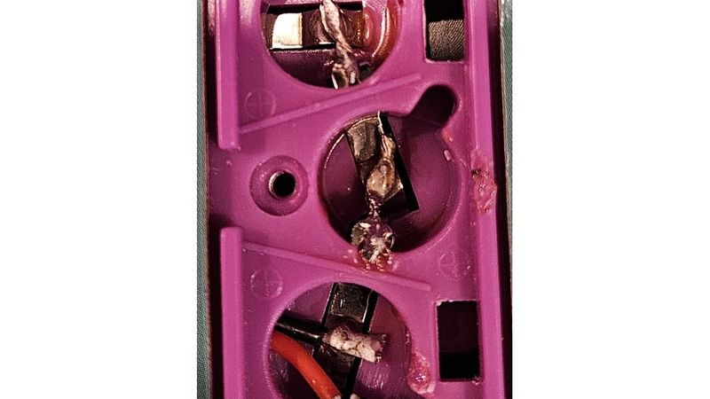
As you can see in the pictures, I set up different male ends into the books. It was easier to work with the green and black ones than the red and black pigtail ones, but they may not be as strong (already had to tighten the screw on one that was pulled out by accident). Within the body of the books, I bridged, then "potted" the battery terminals/cavities for added rigidity.
You should test the functionality of the books before starting. Just connect a bench PSU to the positive and negative leads, then run anywhere from 3-4.2V (lower may still work for some books, but the BMS should prevent the 18650 from supplying power below 3V).
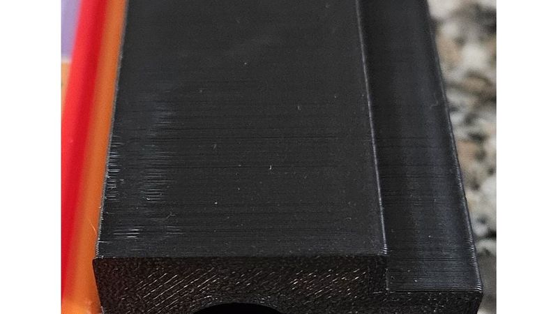
The retainer holder is pretty straight-forward. It has a tolerance of .1mm, so it's a little tight but not too tight, if your printer is dialed in. If your tolerances aren't great, you will want to very slightly scale it up (as an easy pointer, you can just cut the top of this down in your slicer to 5-8mm, print that out, and then test). The center of the holder is wider for the barrel plug, so make sure to route it properly to install and remove the battery retainer.
I used superglue to attach the housing retainer and the green and black male barrel plugs to the body. I used some hot glue for potting the battery cavities and some B-7000 jeweler's glue for the wires that plug into the BMS to keep them sturdy (don't want them ripping out).
I made this in a way for the 18650 to be easily removed, if someone wanted to solder the belts onto the battery and make it permanent, the two inner walls by the cavity would have to be removed (in most slicers, you can just add a negative cube in there and stretch it out the the proper size). If someone needs, and I see a request, I could probably do that for them, if I see a demand.
Printing:
I printed the retainer holder with 3 walls and 10% infill at .2mm height, I think that is actually way stronger than it needed to be, 2 walls would have been fine. I printed the retainer for the battery itself with 2 walls. Printing on a couple Creality K1 Max printers. This should print fine on any printer, even my old Creality CR-10S, just be aware that the tolerances may need looked at.
Notes for safety!
If you're crazy like me and you're fixing a kid's toy, don't let them play with it unmonitored! The superglue could break off, the wires could pull out, the edges could scratch them (I should have added a fillet or chamfer but I was in a rush since I promised my kid's I'd have the book fixed in a few hours), the small leads could bridge if they pull out of the male side... there are a few potential risks with this design in the way that I'm using it. If you're using it for something non-kid-related then there isn't much risk other than environmental water or extreme heat.
I'm going to put this up on Makerworld also, with all the files (I only have my mods in this file so that people go back to the original creator's page for credit).