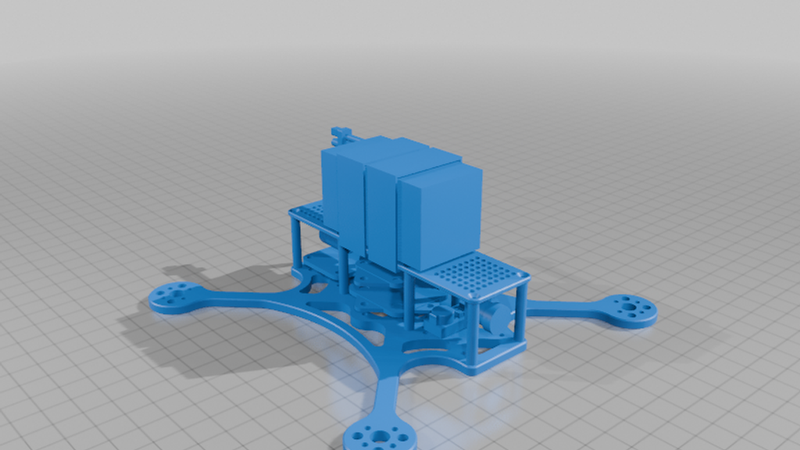
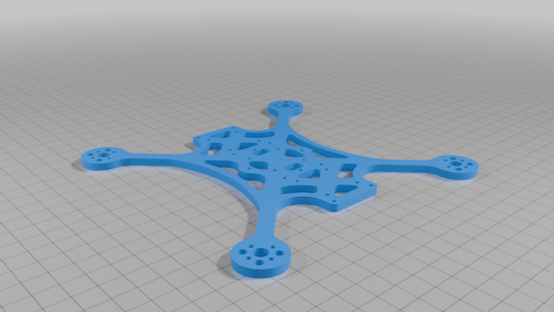
Mirro35 V0.4 drone frame


Description
Intro
Name: Sugalime3D FPV Mirro35 V0.4 drone frame (a.k.a. Mirror35)
Carbon fiber 3.5" propeller TrueX quadcopter drone frame.
Optimized for freestyle:
* Frame durable to crashes
* Enough space and good protective casing for the electronics
* Minimization of resonance interference affecting the gyro sensor
* ...
Timeline
Check regularly for updates; More parts will likely be added if the tests are successful (TPU parts, carbon fiber parts, ...) !
* June 24, 2026: Publication date: Starting with Bottom plate 4,0 mm turned45onXY OPCO, Bottom plate 4,0 mm OPCO, and Top plate 0tilt OPCO
* June 25, 2026: Added Top plate 0tilt DJI OPCO, Top plate 0tilt HDZERO OPCO, Top plate0tilt NC NCS, Bottom plate 4,0 mm NC, Bottom plate 4,0 NC turned45XY
Selected posts from social media of this project (new to old)
https://www.tiktok.com/@sugalime3d_fpv/photo/7655096681079295254
https://www.tiktok.com/@sugalime3d_fpv/video/7648709208719822102
https://www.tiktok.com/@sugalime3d_fpv/photo/7648665066266594583
Specs
Propeller: 3.5"
For 4x M2 D12mm mount brushless motors: Stator 14XX, 15XX, 16XX, 17XX, 18XX, 20XX.
For example: 1405, 1505, 1507, 2004, 1408, ...
For smooth and powerfull punch out freestyle I recommand 1408 or 1507 motor with 3500 - 4350 KV
Recommanded battery: 4S 750-850 mAh LiPo battery (82 - 100 g).
Bottom plate thickness (of the standard/first edition): 4,0 mm
Bottom plate arm width: 7,0 mm
Top plate thickness (CAD file): 2,0 mm
Recommended standoffs: M2 D4.0 (or D3.5) mm
Main/central stack mounting holes: M2 20x20 and diagonally whoop style M2 25,5x25,5 mm
Main/central stack max 2D space: 36,00x36,00 mm using M2 D4 standoffs (O4 Pro is 33,5 x 33,5 mm)
Trunk stack mounting holes: M2 20x20
Frunk stack mounting holes: M2 20x20
Trunk & Frunk stack max 2D space: 29,40 x 29,40 mm using M2 D4 standoffs
Wheelbase (motor to motor diagonally): 182,43 mm
Motor to motor (in a square): 129,0 mm
Available editions so far
Labels:
See descitption CNC service Chamfer editions for the detailed description of the labels
"OPCO" = Outer Perimeter Chamfered Only
"turned45XY" = Turned 45° on XY axis. Arms parallel to carbon fiber pattern.
"NC" = No chamfers
"NCS" = No countersinks
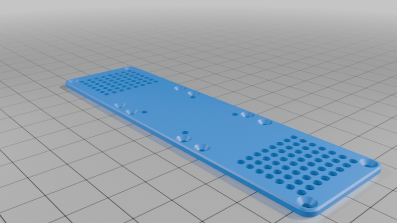
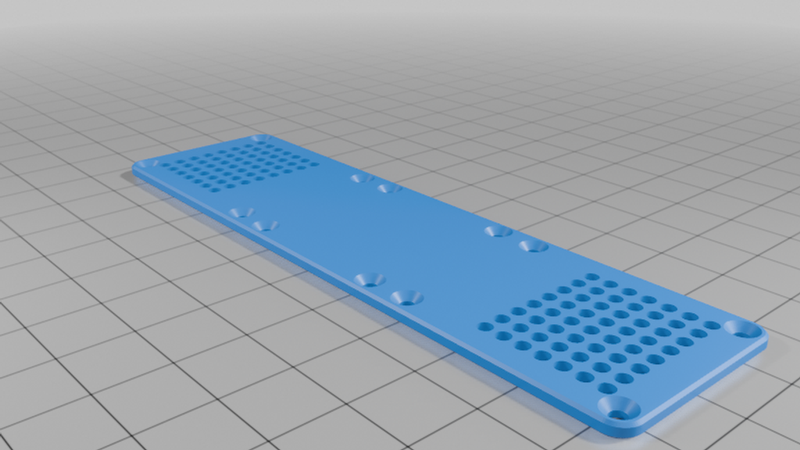
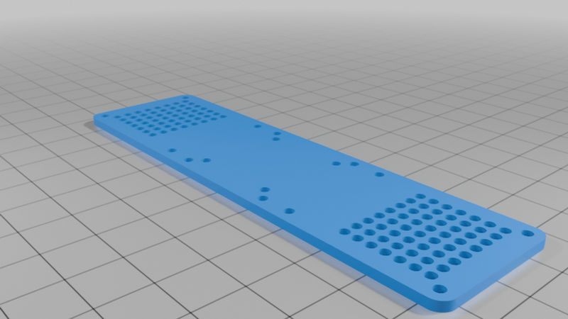
Bottom plate
* 4,0 mm OPCO
* 4,0 mm OPCO turned45XY
* 4,0 mm NC
* 4,0 mm NC turned45XY
Top plate
* 2,0 mm 0tilt OPCO (Mixed VTX mount, priority on M2 25,5 x 25,5 mm )
* 2,0 mm 0tilt OPCO DJI (VTX mount M2 25,5 x 25,5 mm only)
* 2,0 mm 0tilt OPCO HDZERO (VTX mount M2 20x20 mm only)
* 2,0 mm 0tilt NC NCS (Mixed VTX mount 20x20 and 25,5x25,5)
More parts are comming soon (no guarantee !)
After the allready uploaded 0tilt edition top plate has been successfully tested, I will add more (no guarantee):
CHAMFER EDITIONS BOTTOM AND TOP PLATE
* Without any chamfer and without any countersink (cheapest to produce)
* Without any chamfer (second cheapest to produce)
* Designer's edition (director's cut) with maximum amount of meaningful chamfers (most expensive to produce).
BOTTOM PLATE THICKNESS:
* 4,5 mm thick edition / 3,5 mm thick variant with D9-12 Motor holes (Cruiser build) / 3,0 mm thick variant with D9-12 Motor holes (for ultralight build)
TOP PLATES:
* For analog 14mm cam in 45° tilt (small circular cutout at the front
* For 04 Pro cam in 45° (huge circular cutout at the front)
* For stereoscopic 3D (Skyzone dual VTX analog S3D)
TPU PARTS:
* Arm guard
* Motor protector
* Cam mounts
* Antenna mounts
* Cap mount
...
SIZES:
* Also I have some motors which are best for 4 inch, That is why in the far future I'll also make a Mirro40 with roughly this base.
LiPo Crash Protector Cage
L064H037 V0p2 LiPo Crash Protector Cage for drone frame
https://www.thingiverse.com/thing:7370388
Digital FPV
DJI
DJI O4 Pro air unit: Yes !
The air unit 04 Pro can be mounted on the top plate 25,5x25,5 central stack holes. Use AIO in bottom plate central stack. Or use 20x20 ESC in central stack and 20x20 FC in trunk, in this case the rotation sensor, however, doesn't care whether the FC is in the middle, at the back, or at the front of the bottom plate. Accelerometer is not used for PID controller, so it doesn't matter where the FC on the bottom plate is placed. Accelerometer data is only used for crash detection, ANGLE mode, GPS rescue. But even if the FC is in the trunk, data is still good enough for ANGLE and GPS Rescue mode imo.
DJI O4 (Lite) air unit: Yes !
For the 04 (Lite) air unit i recommand to use it with an whoop size AIO in the central stack on bottom plate.
HDZERO
Freestyle V2 VTX: Yes !
The VTX unit can be mounted on the top plate 20x20 central stack holes. Use AIO in bottom plate central stack. Or use 20x20 ESC in central stack and 20x20 FC in trunk, in this case the rotation sensor, however, doesn't care whether the FC is in the middle, at the back, or at the front of the bottom plate. Accelerometer is not used for PID controller, so it doesn't matter where the FC on the bottom plate is placed. Accelerometer data is only used for crash detection, ANGLE mode, GPS rescue. But even if the FC is in the trunk, data is still good enough for ANGLE and GPS Rescue mode imo.
All others
They usually come in standard formats and are relatively small, so they can generally be mounted on the bottom plate—either in a central stack or a trunk stack configuration.
Weight calculation (theoretically)
Bottom plate (without chamfers) = 67,03 cm^2
* 3,0 thick T-700 carbon fiber = 37,2 g
* 3,5 thick T-700 carbon fiber = 43,4 g (Standard arm thickness for 3.5 - 4,0" freestyle drone)
* 4,0 thick T-700 carbon fiber = 49,6 g (Standard arm thickness for 3.5 - 4,0" freestyle drone)
* 4,5 thick T-700 carbon fiber = 55,8 g
* 5,0 thick T-700 carbon fiber = 62,0 g
Top plate (without chamfers) =
Approx 9 g
Designed to international standards
Based on DIN EN ISO 7721 and ISO 10642. And close fit (not normal fit) with screws MX regular (not MX fine).
M3 screws ISO regular M3x0,5:
Screw Clearance M3 Holes: 3,20 mm (clearance close 3,2 not medium 3,4 mm)
M3 90° Countersink: 6.50 mm diameter (not the theoretical max of 6,94 mm)
(with FreeCAD PartDesign_Hole, ISO regular, clearance setting close/fine, results in 3,2 mm hole)
M2 screws ISO regular M2x0,4:
Screw Clearance M2 Holes: 2,20 mm (clearance close 2,2 not medium 2,4 mm)
M2 90° Countersink: 4,40 mm diameter
(with FreeCAD PartDesign_Hole, ISO regular, clearance setting close/fine, results in 2,2 mm hole)
M1.6 screws ISO regular M1.6x0.35:
Screw Clearance Holes: 1,70 mm (clearance close 1,7 not medium 1,8 mm)
M1.4 screws, ISO regular M1.4x0.3:
Screw Clearance Holes: 1,50 mm (clearance close 1,5 not medium 1,6 mm)
CNC SERVICE
You can give the CNC service the STEP files; it contains all the information, including details about the plate thickness and chamfers.
List of services
(No guarantee of legitimacy, these are all the ones I found, not the ones I tested.)
The frame is currently not listed on any of the stores, so you will need to request a quote.
* Made in Canada: CNC drones; CNC Madness; ...
* Made in China: CK-Carbon Fiber Store (Aliexpress store ID 1104334140 or search for 1005012382499688 (item)); FPVdroneframe dot com; PCB Way; ...
* Made in France: FPV CNC drone; ...
* Made in Germany: Ahltec (Inh. Angelika Leonhardt); CarbonForce® GmbH, Carbon Composite AG; CARBON-EXPRESS GmbH, Carbon-Posten und Modellbau (Inh. Sandra Schmidt); CG TEC Carbon und Glasfasertechnik GmbH; ...
* Made in Taiwan: Armattan Productions Co., Ltd; ...
Carbon fiber material international standards
Choose what you consider the best sweat spot for your purpose or choose T-800S if money is not a factor to be considered.
Tensile strength is the factor when it comes to arm breaking. Tensile modulus (stiffness) is the factor for vibrations and resonances that can be transmitted to the gyro.
* T-300: Tensile strength: ~ 3530 MPa. Tensile modulus (stiffness): ~ 230 GPa. The affordable and most used standard.
* T-700S: Tensile strength: ~ 4900 MPa. Tensile modulus (stiffness): ~ 235 GPa. Used on expensive high-quality premium frames.
* T-800S: Tensile strength: ~ 5685 MPa. Tensile modulus (stiffness): ~ 294 GPa. Consumer ready in the future. This aerospace and commercial aviation standard is becoming affordable for the consumer hobby market. By now, some very expensive premium drone frames actually use it.
Plate rotation for carbon fiber rectangle pattern matching arms
For the bottom plate use the STEP or STL file labeled "turned45XY" so that the carbon fiber rectangle pattern runs parallel to the drone frame arms. Then the CNC manufacturer should normally position them correctly using this STEP files. Or use the non labeled if it id different...
ADVICE FOR MYSELF THe DESIGNER (so i never foget in future project exports): In FreeCAD the STEP export has to be saved with "Export single object placement" otherwise it won't be rotated by 45° !
Filets
The fillets are always chosen to be as large as possible (better for durability) and never have a radius below 1.00 mm (standard milling heads have a minimum limit).
The smallest fillet radius used in this project: 2.0 mm (i.e., it can be milled with a D4 CNC).
Chamfer editions & Edition labels
The chamfers are important to prevent the electric cables, the LiPo straps or your fingers skin from being cut.
There are 4 editions:
* NC NCS: Edition is without chamfers and without countersinks. Requires the least milling work. Advantage: The cheapest option.
* NC: Edition is without chamfers (NC = No chamfers) Advantage: The second cheapest option.
* OPCO: Edition is with "Outer Perimeter Chamfered Only". Requires often only a bit more milling work using a buck side chamfer mill.
* NORMAL (Non labeled): It is the designer's version "Director's cut" . Like the designer wishes it to be. Version includes maximum of meaningful chamfers. Disadvantage: A part with a lot of chamfers on both sides can be very expensive especially when holes or radii are small, depending on the capabilities of the CNC manufacturer. The effort and time involved in the milling process can increase significantly. Consequently price can be 2-3x higher than that of the NC NCS version.
Buck side chamfer CNC process
The CNC service typically creates the double sided chamfer using a special drill head (buck side chamfering) that first makes the chamfer on top then on the bottom, or they use a high accuracy plate turning process if the holes are too small for the special drill.
Public example of buck side chamfering
https://www.youtube.com/shorts/9M66unswJ7c
Creating round edges without chamfer milling
The sharp corners can also be rounded off without milling chamfers: They place the part in a in a tumbling drum and they use a sharpening stones tumble vibratory deburring method, or they use other methods to remove the corners sharpness. However, the corners aren't rounded off as much with this method—especially if the manufacturer does not give it a lot of time to it. The edges remain relatively sharp and it doesn't match the quality and smoothness of chamfer milling. COSTS: Sometimes rounding the corners like this is cheaper, sometimes milling the chamfers is cheaper—it depends.
Some of the features of this frame explained
4x stack design:
This frame allows you to mount up to four stacks (3 on bottom plate and 1 on top plate). This is very unique and rarely found on other frames. This provides great flexibility in how you distribute your boards. Even if an huge 25.5 x 25.5 AIO is placed in the center, you can still mount 20x20 hole boards (like for example VTX) in trunk or frunk thanks to standoffs.
Durability and stiffness through springy design:
It has such arches on the sides, front and back; these act as springs that can absorb energy upon impact, thus making it less likely that the arm will break. It also makes the arm shorter, which also makes arm breaking less likely. It also improves rigidity (stiffness), meaning fewer vibrations caused by motors reach the gyro. DISADVANTAGE: Such additional "connecting rods" increase the risk of the drone getting stuck in a tree crown.
For 3.5" sub250: Monoplate lightweight design vs heavier more fragile and problematic interchangeable arm design:
Because it's challenging to build a 3.5" drone under 250 gramms (sub250) with an optimal battery weight ( not undersized bat ) the monoplate design was chosen. This saves the weight of extra screws, pressnuts and sandwich plates. This can make the difference between fake sub250 (totally undersized battery) and true sub250 (perfect battery weight for perfect balance in weight distribution). Another disadvantage of interchangeable arms compared to monoplate design: There is only M2 25mm and 30mm screws available on market. Often, due to the sandwich plates, the 25mm screws are too short and the 30mm screws too long for standard standoffs. A design with interchangeable arms requires 8 additional M3 holes in the frame, which also makes the frame more fragile. Often, with interchangeable arm designs, it's not even possible to change the arm without removing the stack screws, meaning you have to redo everything also, and an interchangeable arm design takes even more time to set up...so often the only thing is you gain is not time but only money if you have a lot of arm breakings (an arm is cheaper then a bottom mono plate)... However, since the monoplate here is 4.0 mm or 4,5 mm thick—and arms on 3.5-inch drones break significantly less often than those on 5-inch models—the monoplate design makes perfect sense for 3.5-inch drones.
Unperforated top plate design:
The top plate has an unperforated pad area in the middle for multiple reasons: 1) This makes it much easier to glue on an universal rubber pad. 2) This also provides more pad surface area, which reduces slipping. 3) The pad has much surface so it adheres very well 4) You don't get any dirt on it because the pad isn't glued over holes where dust and dirt can accumulate. 5) Furthermore, no forces in the form of a pattern act on the LiPo when it is compressed... With cut-out patterns, there is a higher risk of the LiPo being damaged as a result...
Durability and safety through round circular arm ends:
Advantages
* In judo sport you learn to roll when thrown to the ground. This reduces the impact energy and the risk of injury. Perfectly rounded arm ends improve rolling in case of a crash. The better ability to roll reduces the likelihood of an arm fracture. The duration of crash energy transfer to the frame is reduced, making it less likely for the material to break...
* The rounder a vehicle body, the less likely it is to injure you, others, or valuable things in the event of an unintended crash.
* This design provides robust hard carbon fiber protection all around the motor, not just at a 45° angle.
* You can see with my youtube video "FreeCAD | Design a arm/motor guard for existing drone frame" how complex and difficult it is to design a motor guard from a scanned photo when the arm has complex shape. The arm and motor guard is significantly easier to design when everything is round. Anyone can design their own individual motor guard relatively easily and quickly. With a round design, I don't need the time-consuming photo scanning method...
* TPU parts are heavy, and a round TPU motor guard will have less TPU material and will be lighter if the carbon fiber foundation for it is round. Most people design their motor guards to be round anyway. So why not make the carbon fiber arm round as well ? That would save on TPU weight...
Disadvantages
* Hard protection is only available for one motor size, or at least for all smaller motors. Larger, wider motors have 0% carbon fiber protection. So it is less flexible to different motor sizes.
* There is maybe less hard carbon fiber protection against impacts that occur at 45°.
DEVELOPMENT FUTURE
Planned changes for the next version:
* No
DEVELOPMENT HISTORY
PREVIEWS VERSIONS:
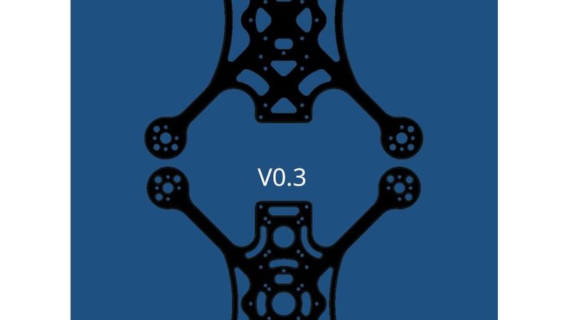
Mirro35 V0.3 drone frame
https://www.thingiverse.com/thing:7365972
Mirro35 V0.26 drone frame
https://www.thingiverse.com/thing:7287512
(There are some FreeCAD videos included, with drawings that are certainly interesting to see, even if a lot of dimensions are no longer quite accurate with V0.3...)
GUARANTEE
This version is the first version i will order at a CNC service. Use at your own risk ! It is in version 0.4 and not 1.0 ! I guess it should work. However, it has not been tested yet. Big and/or small errors are possible. The design is still in the prototype phase. I have not ordered and tested the part through a CNC service yet. Therefore, the part may still be revised and then appear as V0.5 on a new page. Maybe tests will be successful and this will be the final version of the Mirro35 drone frame.
COPYRIGHT & CREDITS
PRIVATE USE:
You are allowed to download and copy and modify the frame for private use and upload and publish a CAD mod/remix with credits (My name and the link to this one); please note the license terms specified below. For non-commercial purposes, i.e., hobby videos or picture in the internet, me or the name of the frame I don't expect to be mentioned in videos or pictures or description. However, I appreciate it if you mention the name of the frame and the designer in the vid/pic itself or description.
COMMERCIAL USE:
I permit to download and use and copy and modify for commercial sales. However, I expect the designer name and product name to be mentioned in the title or description of the product with the product name: "Mirro35" or "Mirror35" and the designer name :"Sugalime3D FPV" or "Sugalime3D FPV design" or "designed by Sugalime3D FPV".
Example: [Your Brand] Sugalime3D FPV Mirro35 drone frame TrueX 3.5 inch carbon fiber Mirror35