Outboard Motor Bracket V2
Description
Outboard Motor Bracket V2
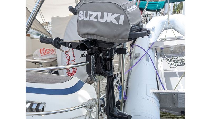
This is version 2 of my 3D printed outboard motor bracket for mounting a small outboard on a curved sailboat pushpit rail. It is a replacement and update for my V1 design (https://www.thingiverse.com/thing:6470249).
V1 worked well for about 4 years in a saltwater environment, mostly with a Suzuki DF2.5 outboard. It eventually started showing cracks, though it was still functional. V2 keeps the same basic design idea, but improves the materials, hardware, and assembly method.
Important safety note
This is a DIY bracket. It is not professionally rated or certified. V2 has only been dock-tested so far with a small Suzuki DF2.5, about 30 lb. V1 was used for 4 years, mostly with the same motor and only very occasionally with a heavier 87lb motor.
Do not assume this design is safe for larger motors. Inspect regularly. Use at your own risk. You are responsible for deciding whether this design is suitable for your boat, rail, motor, and conditions.
Basic design idea
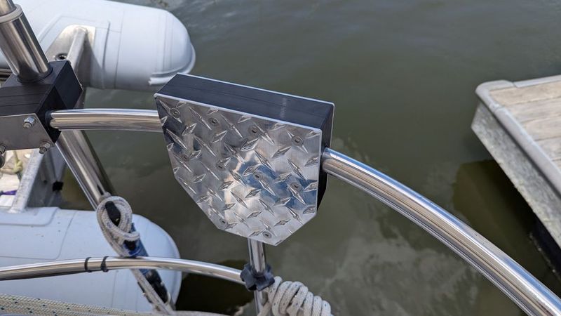
The 3D printed parts are used as form-fitting inserts around the curved pushpit rail. Metal is used where strength and wear resistance matter.
The bracket consists of:
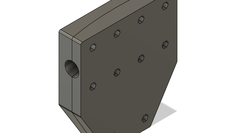
* Two TPU printed inserts
* Two 1/8" aluminum clamp plates
* Ten M6 stainless hex coupling (barrel) nuts captured inside the printed inserts
* Twenty M6 flat-head socket screws, ten from each side
The screw pattern captures the rail. Even if the printed inserts were damaged, the metal plates and screws should still help keep the bracket attached to the pushpit rail.
What changed from V1
V1 used polycarbonate printed parts with an aluminum plate on one side and a carbon fiber/epoxy face on the other side. It also used hidden glassed-in weld nuts, which worked but were awkward to build and the original weld nuts became hard to source.
V2 changes:
* Both motor clamp faces now use 1/8" aluminum plates.
* The printed inserts are slightly thinner than V1.
* The hidden weld nuts are replaced with simple M6 hex coupling nuts.
* Screws go in from both sides into the same internal coupling nuts.
* The printed material is now TPU instead of polycarbonate.
Polycarbonate did work for several years, but it is very rigid and does not tolerate rail-fit errors very well. It can also develop stress cracks after exposure to petroleum products such as oil, grease, and gasoline. Outboard motors tend to have all of those nearby.
For V2 I used Bambu TPU for AMS, which is 95A hardness. People often think of TPU as soft rubber, but with enough walls and infill this material prints into a tough, fairly hard part with a little compliance.
Print settings used
Printer: Bambu X1C
Nozzle: 0.4 mm
Material: Black Bambu TPU for AMS, 95A
Walls: 7 perimeters
Top/bottom layers: 6
Infill: 25% gyroid
Orientation: print each insert with the aluminum-plate facing surface down on the build plate
Black filament is recommended for UV resistance.
Other printers and TPU materials may work, but I only tested the settings above.
Default design parameters
The included Fusion 360 file has user parameters that can be adjusted for your rail.
My rail is about 25 mm actual outside diameter. I set:
* `RailDiameter = 25.5 mm`
* `CurveRadius = 500 mm`
The total printed thickness of the two inserts is 41 mm. The M6 coupling nuts I used are 40 mm long, leaving about 1 mm for compression when the bracket is tightened.
Hardware used
You will need:
* 10 pcs M6 x 1.0 stainless hex coupling nuts, 40 mm long
* 1 extra coupling nut to drill out and use as a drill guide
* 20 pcs M6 x 20 mm stainless flat-head socket screws
* 1/8" aluminum plate for two clamp plates
* Tef-Gel or similar anti-galling / anti-corrosion compound
I used 304 stainless hardware because it is cheap and easy to find online. 316 stainless would be better for saltwater if you can get it.
For the aluminum, I used 1/8" polished 3003 diamond plate. Diamond plate looks good, hides scratches, and is easy to source. Smooth 1/8" aluminum plate should also work.
Make sure your countersink bit matches your flat-head screws. Metric flat-head screws are often 90°, while many imperial countersinks are 82°.
Making the bracket
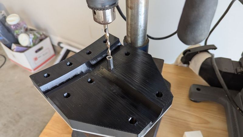
1. Print the two main inserts and the nut drilling jig.
2. Take the extra M6 hex coupling nut and drill out its threads using a 6 mm or 1/4" cobalt drill bit. Use the printed nut drilling jig to hold the nut straight. A drill press is highly recommended. Stainless steel can work-harden, so use cutting oil and drill at a reasonable speed.
3. This drilled-out nut becomes the drill-guide nut.
4. Use one printed insert to trace the aluminum clamp plate outline onto the aluminum plate.
5. Cut out the aluminum plate. I used a regular miter saw. Smooth and round the edges afterward.
6. Attach the aluminum plate to the printed insert using basting tape or double-sided tape. The tape only holds the plate in place while drilling.
7. Put the drill-guide nut into each hex pocket, one at a time, and drill through the aluminum plate.
8. Flip the part over and countersink the holes for the flat-head screws.
9. Repeat the same process for the second aluminum plate and printed insert.
10. Install all 10 coupling nuts into one printed insert. Attach its aluminum plate using 10 screws.
11. Hold that half of the bracket against the pushpit rail.
12. Place the second printed insert and aluminum plate on the other side of the rail.
13. Install the other 10 screws from the opposite side.
14. Use Tef-Gel on the stainless/aluminum/thread contact areas. If you want more thread retention, blue Loctite may be used instead, but I used Tef-Gel for saltwater anti-galling and corrosion protection.
15. Tighten evenly and inspect the fit.
Files included
* 3MF print files
* Fusion 360 F3D file with user parameters
* Photos / screenshots
I did not make DXF files for the aluminum plates. I traced mine from the printed part. If you want DXF templates, they should be possible to create from the included Fusion 360 file.