Needle Cutter Tool for CNC machine
Description
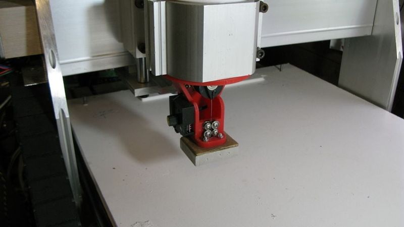
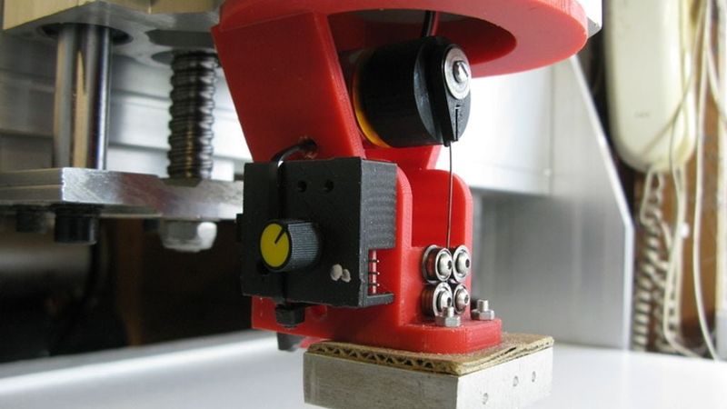
This design is for a needle cutter for a CNC machine.
Needle cutters are useful for cutting accurate designs in 5mm thick paper-backed foam board commonly found in art and craft shops.
In the UK these sheets are commonly available at the Hobbycraft stores.
Foam board is especially useful for making cheap radio controlled aircraft.
In addition to foam board, I have tested this cutter on corrugated cardboard amd thin card as used for cereal boxes along with thin balsa sheets.
This needle cutter should fit in a standard CNC spindle holder but as the original design files are available you can modify it as needed for any machine.
The principle of operation is that a fine needle is moved up and down very fast as the head moves across a workpiece. You generally need a minimum of 10 to 15 strokes per mm of movement.
This design uses 0.6mm diameter piano wire.
In the UK, piano wire is easily obtained from B&Q stores and online.
Look for the Diall brand in UK hardware stores.
The exact dimensions of the piano wire are not critical as long as
it is a good fit in the guide. I measured mine at 0.65mm diameter.
The motor is a 1000KV brushless model motor. Any similarly sized motor
should be fine. I used a standard speed controller and a radio control
servo tester to set the speed. Every motor in my spares box seems
sufficiently powerful so motors are not critical to a functioning design.
I run mine from an external 12v power supply at about 3000rpm.
I measured the speed using an optical tachometer but this is unnecessary.
Just set the speed to what seems quite fast, not more than 50% full
speed seems to work well.
Having carried out quite a bit of development before this design, there
are a few useful design parameters which seem to give good results:
Use a 0.7mm MIG welding tip as a wire guide. These can be bought very cheaply
from AliExpress and other online vendors.
I also tried using a ball inflation needle. This works but it tends to flex
too much and gets quite hot in use. Excessive temperature will tend to soften
the PLA of the body of this cutter.
Using 0.6mm piano wire: Mig wire works but piano wire is better.
Thicker piano wire will be stiffer and requires a slightly longer
route through the guide. Thus you need a slightly bigger body.
You may have difficulty sourcing suitable guides for very thick wires.
The kerf formed by 0.6mm piano wire is very thin and parts tend to stay
in place during cutting.
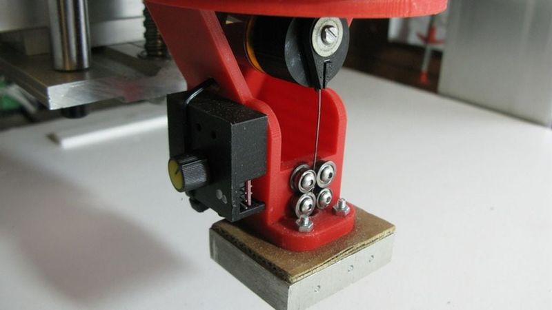
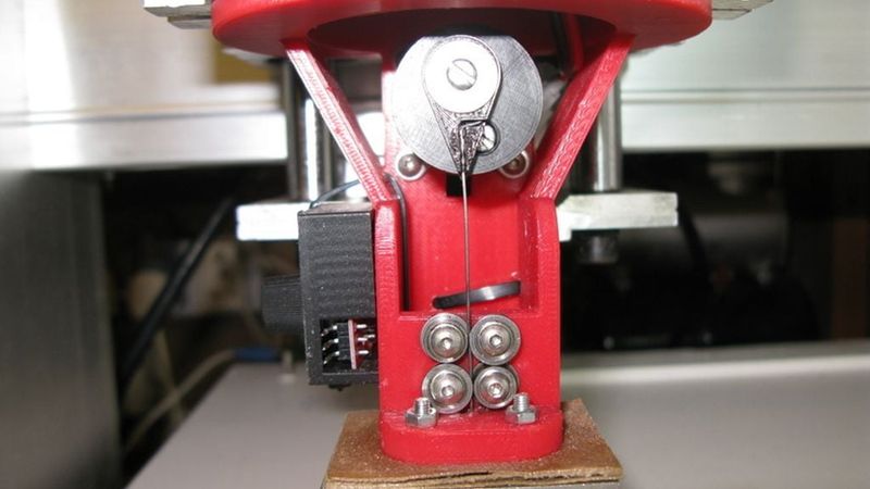
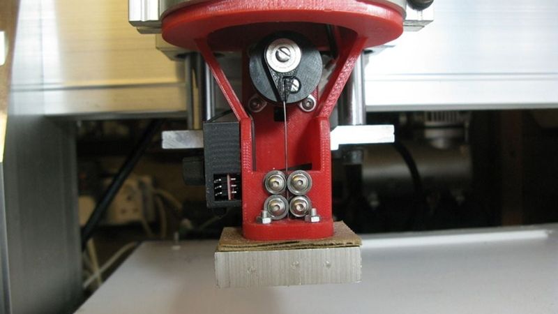
BEARINGS:
Use small bearings to guide the wire into the needle guide.
Without these bearings, the guide can get quite warm and distort the
3D printed parts. Also you increase the wear on the sides of the needle.
I used 8mm diameter x 4mm thick x3mm hole flanged bearings but anything similar could
be made to work.
The minimum length of the needle from tip to guide should be about 75mm.
If you make it shorter there are much bigger bending forces on the needle
for a given movement. If you make the needle-to-guide distance too long
then the needle will tend to buckle or be thrown from side to side at
higher speed. So in both cases you will increase the fatigue rate of the needle.
Use some thin oil to help lubricate the needle in the guide.
HEATSINK:
As the needle may get hot after prolonged use, it may be a good diea to
provide the mig-tip-guide with a heatsink. I used a block of aluminium
from another project. Just drill a 5.5mm hole and press-fit the mig tip.
Use some heatsink compound to help conduct the heat away.
Short runs will be fine without a heatsink but if the guide heats up
then there is a risk of deforming the main 3D-printed plastic body.
Alternatively you can improvise a heatsink from a stack of coins and washers
all drilled with a 5.5mm hole and assembled over the mig-welder-tip guide.
It is also a good idea to provide some thermal insulation between the
heatsink and 3D printed carrier. I used a piece of currugated cardboard which
seems to work well.
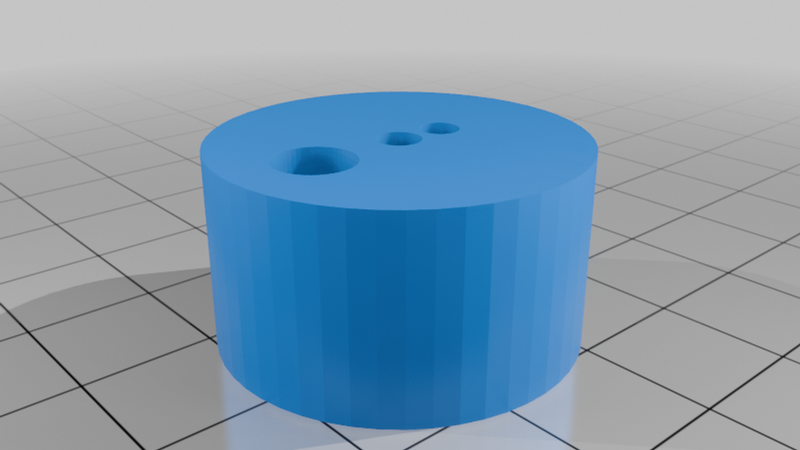
FLYWHEEL:
THe flywheel must be balanced. There is a hole provided into which you
screw an M3 screw and one nut until it is below the front surface.
On the rear you add two more nuts. These two nuts form the drive peg
which locates into one of the holes on the front of the motor spindle.
You cannot rely on just the friction of the spindle to hold the flywheel
in place. A small amount of cyano glue on the spindle may help to
prevent the flywheel from sliding forward along the shaft.
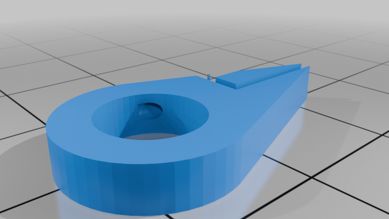
BANJO CONNECTOR:
A small bearing (I used 8x4x3 flanged bearing) is screwed to the offset
hole in the flywheel through the banjo connector. Use M3 screw and a small washer.
The banjo connector holds the piano wire in place.
Often a small drop of cyano glue may be needed to keep the wire in the slot.
PIANO WIRE:
The piano wire needs to have a Z-bend formed in one end to fit the banjo
connector. Good tools are Z-bend pliers (hobby shops) but you can do the same with
normal small long nose pliers. The length of the piano wire should be such that it is only
slightly visible when fully 'up' in the cutter.
Sharpen the tip of the piano wire needle using a whetstone. I do this in situ
by running the motor and carefully holding the grit-stone such that
I get a very sharp point on the needle.
NEEDLE THROW 8mm:
Although foam board is typically about 5mm thick, you seem to need about 8mm
total movement in order to guarantee a good cut. Boards tend to be far less flat
than you may think and in any case can be difficult to hold down against
your waste board (use another piece of foam board for this).
If you need to cut thinner material such as card, use a shorter throw
and needle as this is less likely to buckle under load.
I use weights to hold down the foam boards whilst cutting. I tried a vacuum
system but it wasn't very good. Maybe I will redesign it another time.
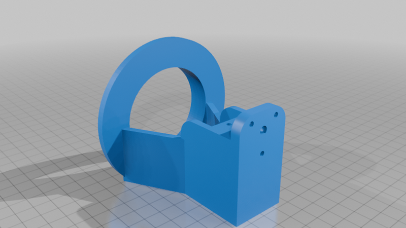
3D PRINTED BODY:
I used PLA-Plus on a Prusa MK4S. 20% infill with supports.
You may wish to add some extra holes to mount your speed controller
and servo tester by way of small cable ties or similar.
Keep all wires well clear of any moving parts.
I didn't add it to this model but it may be a good idea to
extend the top in order to add a plastic safety guard around the
motor and flywheel. A clear plastic bottle may provide some
protection from a broken needle exiting the machine.