Pico hexapod robot

Description
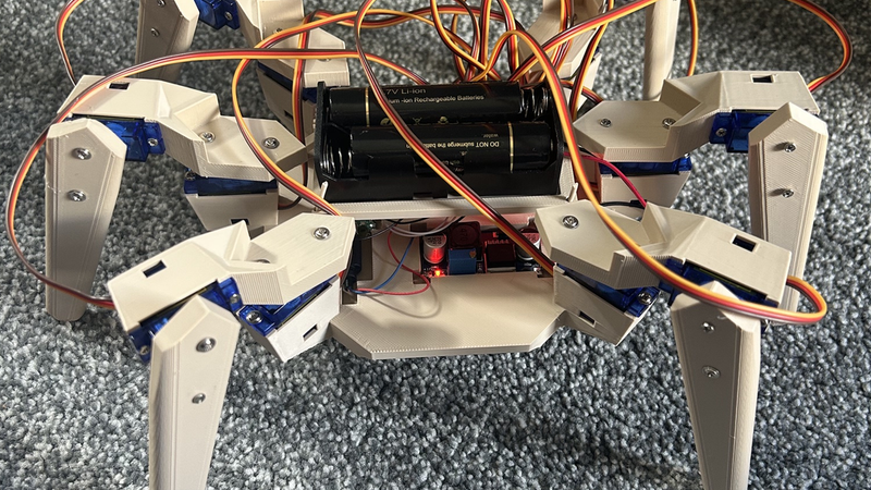
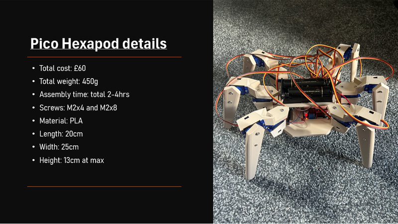
This is a 'small' hexapod robot made (mostly) for the Pico builders competition.
Instructions also attached in text file if you can't be bothered coming back to this page
The price of all the parts excluding the 3d printed parts and any tools comes to around £50-60 depending on the specific brand of each part (amazon links at bottom)
Part list:
1x Pi Pico w/2w (no headers)
1x PCA9685 servo driver (others may work, only one tested)
1x buck converter (LM2596 used in the project)
2x 18640 batteries
1x series 18650 battery holder (80mm by 40mm)
12x SG90 Servos (MG90S highly recommended)
~30x M2 8mm self tapping Screws (Depending on how many you lose)
12x M2 4mm Screws (Usually included with motors)
A few wires to solder into components (can be bought or 'borrowed' from most old chargers)
1x Sacrificial microUSB cable
6x Lower legs
3x Upper legs
3x Mirrored Upper legs
1x main body
(SOLDERING KIT AND VOLTMETER IS NECESSARY)
instructions:
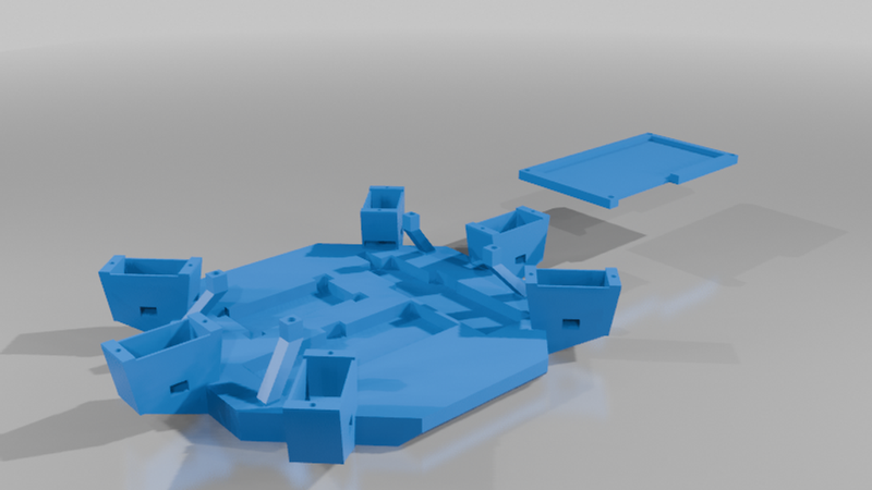
The first thing you need to do is print the parts, you'll notice that the Main body has cut-outs for all the components.
After is the most tedious part, which is soldering:
You need to solder the battery holder to the buck converter: red to IN+ and black to IN-
This is a good time to check that your batteries supply around 7-8v with your voltmeter , then adjust the tiny screw on the buck until the voltage reads 5.5v or similar.
The buck is going to need to be split between your Pico and you servo driver. This means that you need to strip the microUSB to expose the black and red wires inside. Then twist these together with two other lengths on red and black wire, these will go to the driver. These two twisted wires the get soldered into the converter, red to OUT+ and black to OUT-.
Next comes the driver, one one side there should be solder points that read: GND OE SCL SDA VCC and V+, this is where you solder you connections to the Pico. There should also be a small green box with a hole for V+ and GND. The black wire from the buck should be screwed into the green GND section and the red into V+. If later there is no power going to your servos, you may need to solder the red into the V+ solder hole on the side.
Next is the connection from the Pico to the driver, which is very easy to mess up. These connections are solely made with the wire either bought or harvested from other cables.
Connections:
PICO --> Driver
GND --> GND
VCC --> 3.3V OUT
SDA --> GP4
SCL --> GP5
Note: If you plan on coding anything from scratch, GP4 and 5 are not the normal configuration, use of GP0 and GP1 is recommended
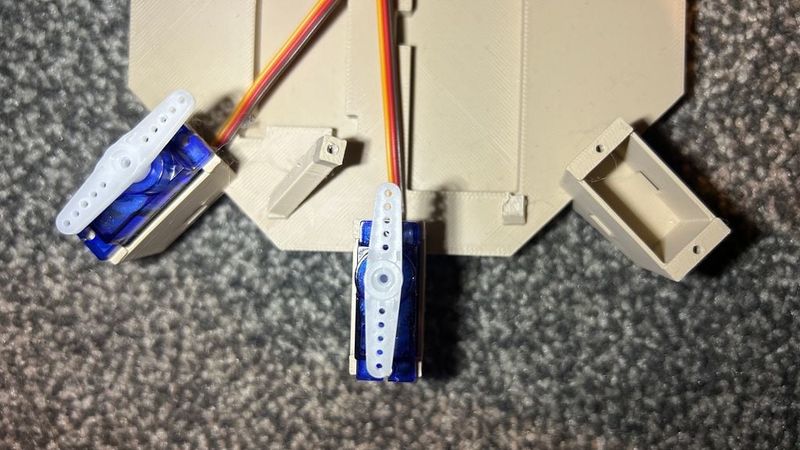
Before you place all components in, the servos must be installed before to make your life easier, there are 6 slots for servos on the base, with a small hole in each. the long wire needs to be slid through this hole before the servo.
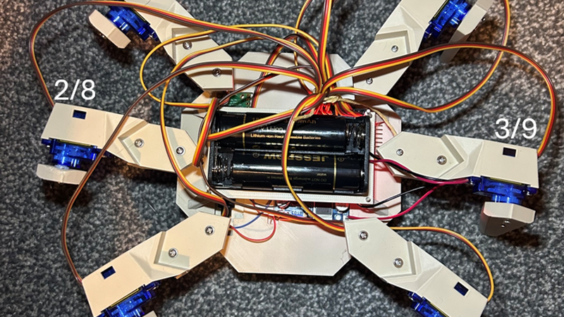
After this step, you are now able to slot each component into their slot on the main body, to conserve space the battery is on its own level over everything else, made to be attached with small lengths of filament and super glue this means it must not be permanently installed until you are sure everything works. The diagram shows where each servo corresponds. Please make sure that the black, red and yellow match up on the slot and the wire.
Once checked for functionality, you can run the 90° text in Thonny to automatically turn all motors to 90°, then using the long straight horns and M2 4mm screws, attach the horns as shown in the second diagram.
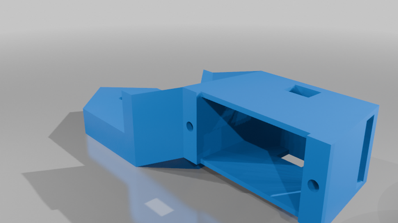
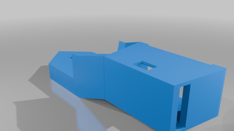
The Upper leg is the next component, you should have 6 in total with 3 being mirrors, these upper legs also need servos in them, so as with the main body, slot the wire through the hole first, then the servo. The process of testing, putting to 90° and screwing in with both 8mm and 4mm should be repeated with each leg.Then, using 2 M2 8mm screws, the holes in the leg should line up with the holes in the servo horn on the main body. They should be attached as shown in the 3rd diagram, so each side has either the mirrored or normal leg. If the sets of leg are incorrect, it will lead to much more instability.
The lower leg is the simplest step. Simply line up the two holes with the two on the horn and fix in place with two more 8mm screws each, there are no mirrored parts.
Code: code is found as an attached file but it does the following:
Using the Pico AP mode, it creates its own network you connect to like a Wi-Fi.
This allows you to visit a html website that has simple walk function, as well as turning both direction. it also features individual sliders for each joint.
The website name will be displayed in Thonny for you to connect to e.g: "Open Browser and type address: http://123.456.7.8'".
What you need to do in the code:
Its very simple really just change the line "ap_mode('name', 'password')" to what you want your name and password to be.
Then run it in Thonny to see your website url
Amazon links:
Servos: https://www.amazon.co.uk/dp/B0GLG2YGJ3
PCA driver: https://www.amazon.co.uk/dp/B0DVCH2BV2
Pi Pico 2W: https://www.amazon.co.uk/dp/B0DNZKYGWP
Buck converter: https://www.amazon.co.uk/dp/B0823P6PW6
Battery holder: https://www.amazon.co.uk/dp/B09GY6CJ7Y