Pico Calculator
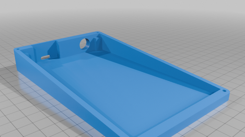
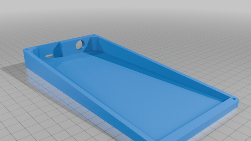
Description
Pico Calculator
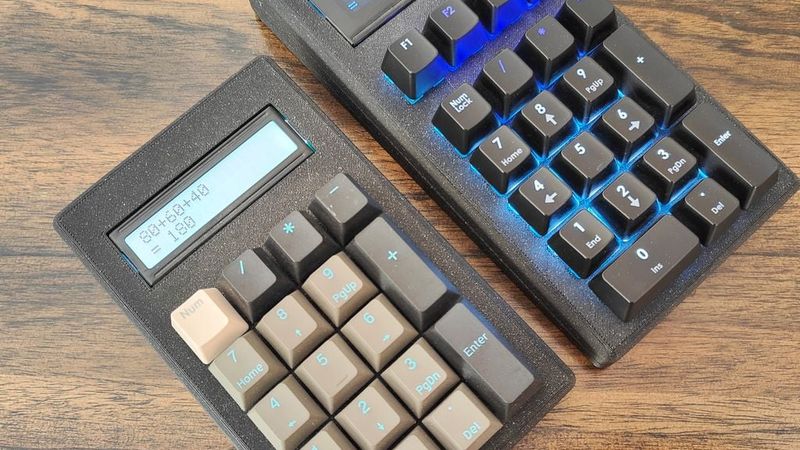
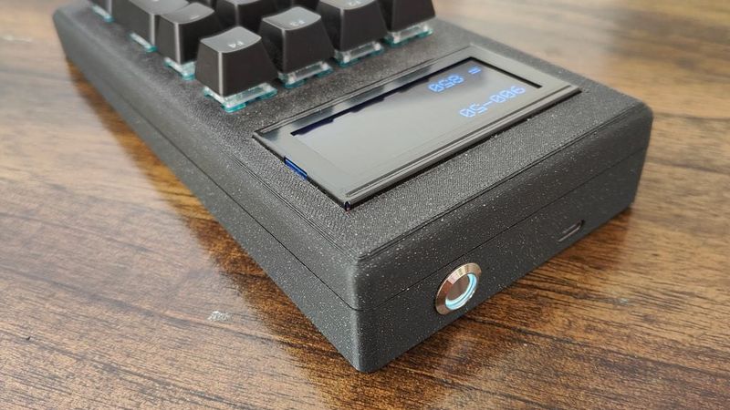
Pico Calculator is a portable mechanical-switches calculator platform powered by the Raspberry Pi Pico. If you are a fan of mechanical keyboards, this is a fun project for you.
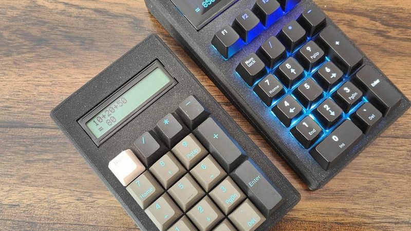
The project currently includes two versions:
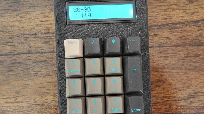
Pico Calculator
A lightweight and portable version featuring:
- Portable lightweight design
- 1602 I2C LCD
- Beginner-friendly assembly
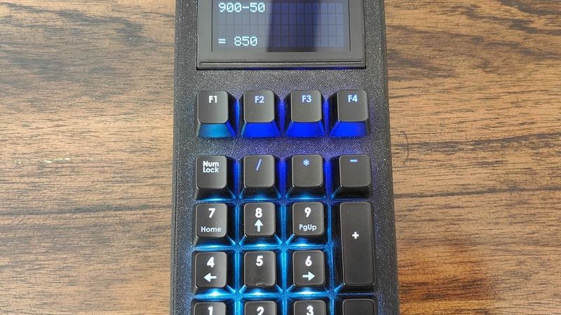
Pico Calculator Plus
An enhanced desktop-oriented version featuring:
- Larger 1604 I2C LCD display
- 4 utility shortcut function keys:
- Percentage calculation
- Percentage difference calculation
- Customizable currency conversion through firmware (default: USD to BHD)
- Clear functionality
- Independent power management for LCD and key backlighting
- LED key backlighting (optional)
Parts Needed
Shared Components
Controller
- Raspberry Pi Pico
Power System
- 3.7V Li-ion battery
- TP4056 USB-C Charging Module with Protection
- 5V Boost Converter Module
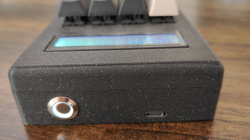
- 12mm Latching Power Switch with LED light
- JST Connectors / Plugs
Input Components
- Your preferred MX Mechanical Switches
- Keycaps
LCD Components
- I2C LCD Backpack Adapter
Hardware
- M3 screws
- Wiring
- Solder
Pico Calculator
- 1602 16x2 HD44780 LCD Display
Pico Calculator Plus
- 1604 16x4 HD44780 LCD Display
Optional LED Backlight Circuit
- 3mm LEDs for key backlighting
- Resistors
- 2N2222 transistor
- Dedicated boost converter module for the LED circuit
- Transparent legend keycaps
Wiring
LCD (I2C)
- SDA → GP0
- SCL → GP1
- VCC → 5V (from boost converter)
- GND → GND
Switches
All switch inputs are connected directly to available GPIO pins on the Pico and wired to VCC.
The following GPIO pins are used for button inputs:
`GP2, GP3, GP4, GP5, GP6, GP7, GP8, GP9, GP10, GP11, GP12, GP13, GP15, GP16, GP17, GP18, GP19, GP20, GP21, GP22, GP26`
GPIO assignments are defined in the firmware and can be adjusted depending on enclosure layout to simplify assembly.
Power System
- 3.7V Battery → TP4056 IN+ / IN-
- TP4056 OUT+ → switch → Boost Converter IN+
- TP4056 OUT- → Boost Converter IN-
- Boost 5V OUT → System VCC
- Switch LED → 3.3V → GND
(make sure your switch includes a built-in resistor or use an external resistor)
- GND → Common ground (all modules)
Optional LED Circuit (Plus Version)
- GP14 → Base of 2N2222 (through resistor)
- Collector → LED cathodes
- Emitter → GND
- LED anodes → 5V via resistors
- Powered by dedicated boost converter rail
Firmware
Install CircuitPython on your Raspberry Pi Pico, then download the required LCD library from the GitHub link provided below.
Finally, choose either `calculator.py` or `calculator-plus.py`, rename it to `main.py`, then copy it to the device root directory.
Two firmware versions are provided:
Pico Calculator
`calculator.py`
- Standard calculator functionality
- Single press `CLS` = Backspace
- Double press `CLS` = Clear all
- LCD power management
Pico Calculator Plus
`calculator-plus.py`
- Backspace (`NumLock`) and clear functions (`F1`)
- Percentage calculation (`F2`)
- Percentage difference calculation (`F3`)
- Currency conversion (`F4`) — customizable via code
- LED + LCD power management
Step-by-Step Installation
1. Install CircuitPython on the Raspberry Pi Pico
2. Download and copy the required LCD library to the `/lib` folder:
https://github.com/dhalbert/CircuitPython_LCD/tree/main/lcd
3. Rename the selected Python file (`calculator.py` or `calculator-plus.py`) to `main.py`
4. Copy `main.py` to the device root
5. Done.
Tips
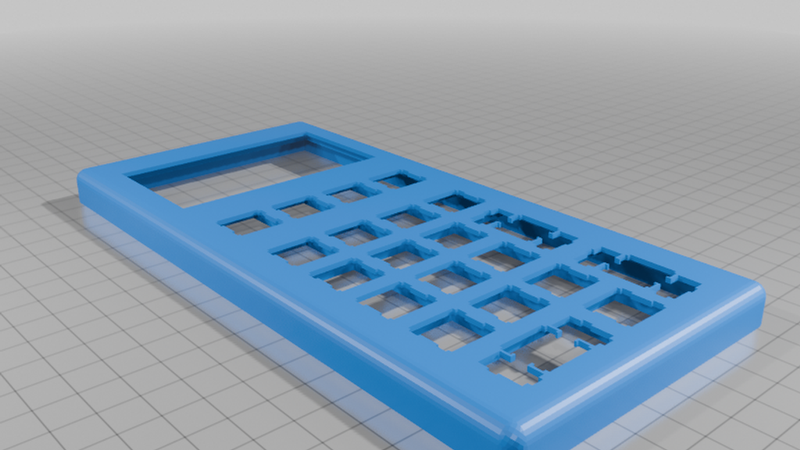
- Both the LCD and switches are designed for a snug fit inside the enclosure. A small amount of hot glue can be used to secure the LCD if needed.
- It is recommended to first wire the LCD and switches to the Pico, install the firmware, and fully test the calculator before adding the battery and charging circuit.
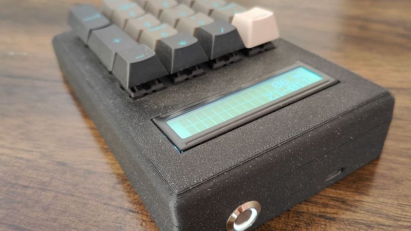
- The enclosure exposes only a single external port for battery charging. The charging module can be secured using hot glue.
- The Pico is intended to remain inside the enclosure after flashing since no further interaction is normally required.