Quickchange robot end adapter.
Description
Quick-Change Robot End Effector / Tool Adapter
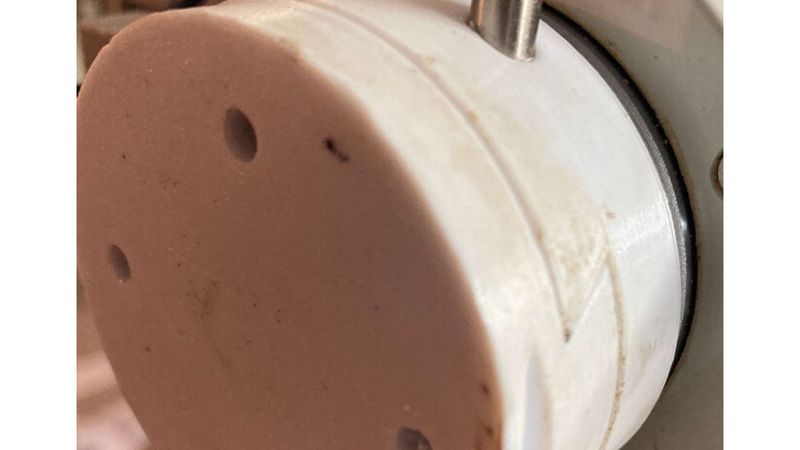
This is a robust, mechanically automated Quick-Change Robot End Adapter designed for light to medium industrial or hobby robotic arms. It enables a robot to autonomously swap its own end-of-arm tooling (EOAT) without requiring pneumatic lines, solenoids, or external actuators just to operate the lock mechanism.
Instead, it utilizes a clever, purely mechanical push-to-lock / push-to-unlock sequence driven entirely by the robot’s own positional movements and the rotation of its wrist (5th axis).
Technical Specifications & Features
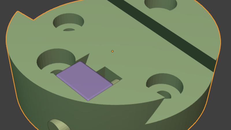
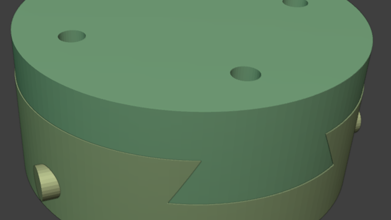
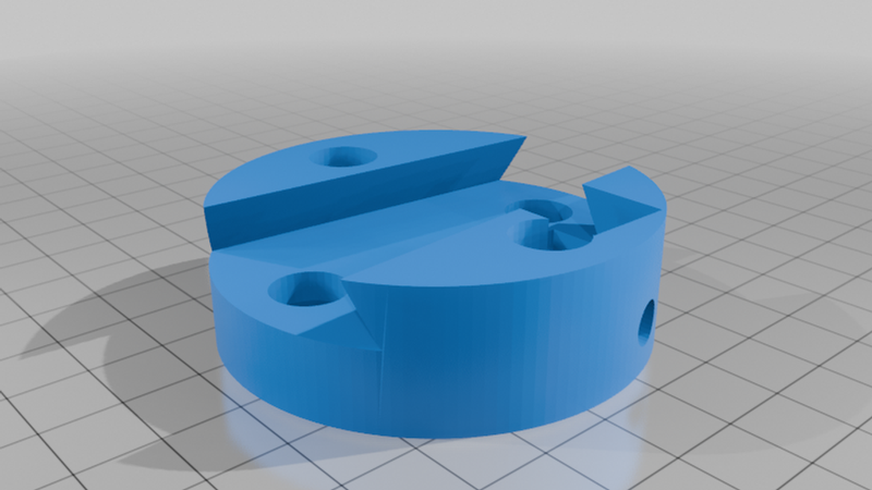
* Dovetail Alignment Interface: Features a precision-engineered dovetail slide tracking system. The angled geometry ensures self-centering, high repeatable accuracy, and exceptional rigidity against torsional and bending moments during high-speed movements.
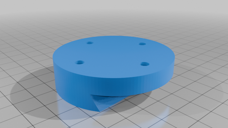
Robot-Side Mounting Interface: Pitch Circle Diameter (PCD): 41.0mm (4 holes spaced 20.5mm from the center).
* Hardware Compatibility: Designed for M4 bolts (4mm clearance holes). Perfect for matching standard small-to-medium robotic wrist flanges.
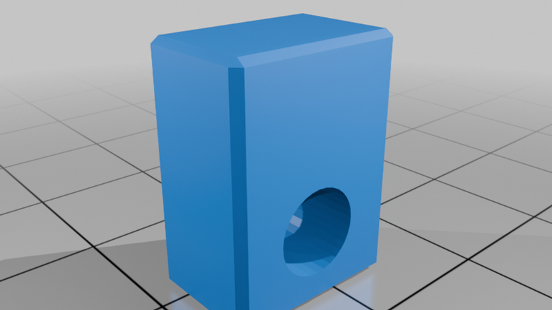
* Lock Mechanism Core: Utilizes a standard Ø6mm x 60mm steel pin/shaft as the internal key shaft. This ensures high shear strength and smooth mechanical sliding without relying entirely on plastic-on-plastic interfaces for structural security.
Autonomous Locking & Unlocking Logic
The defining feature of this adapter is its zero-energy internal locking mechanism. The robot operates the lock by utilizing solid environment fixtures (like a post, table edge, or the tool rack itself):
1. To Lock: The robot slides the dovetail into the tool side, then pushes the exposed lock shaft forward against a solid object. This drives the internal Ø6mm key shaft into its locking detent, securing the tool flange.
2. To Unlock: The robot rotates its 5th axis by 180 degrees (inverting the mechanical alignment relative to the tool rack/push-block), and pushes the opposing side of the lock shaft against a surface, clearing the detent and releasing the tool seamlessly.
Print Settings & Recommendations
To ensure structural integrity and tight tolerances for the dovetail interface, please use the following guidelines:
* Material: PETG, ASA, or ABS are highly recommended for impact resistance and mechanical durability. PLA can be used for light-duty modeling but may creep under constant structural load.
* Infill: 40% to 60% (Gyroid or Grid pattern for balanced multidirectional strength).
* Wall Loops / Perimeters: Minimum of 4 to 5 walls to ensure the bolt holes and dovetail tracks are solid plastic.
* Layer Height: 0.2mm or finer. Lower layer heights provide smoother dovetail surfaces, minimizing friction and reducing the break-in period.
* Supports: Minimal. Orient the parts flat on their primary mating faces. Use support-enforcers only for the internal bridging of the lock shaft tunnel if your printer struggles with long horizontal bridging.
Required Hardware
* 4x M4 Bolts (Length depends on your specific robot flange thickness)
* 1x Ø6mm x 60mm Ground Steel Pin / Shaft (Can be cut from a linear rail rod or high-strength steel rod)