Magsafe Meshtastic case
Description
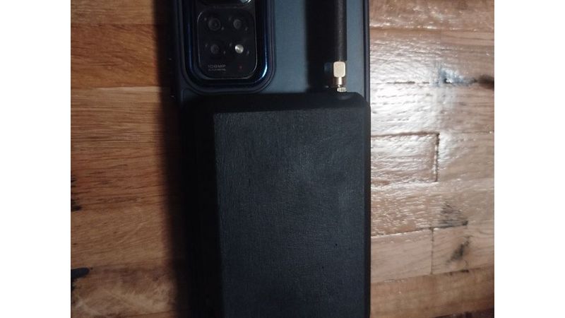
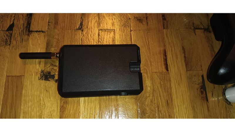
this is a Magsafe Case for a flattened Xaio NRF52 Device.
mine is running Meshtastic
i did take some inspiration from this design:
https://www.thingiverse.com/thing:7285462
especially regarding the flattening of the NRF52
it is somewhat tedious to do but achievable
check out gizmobuddys Guide on how to do it
at the bottom of this Post i also have a write-up on how i did it with fairly basic tooling
modifying his design would have been more work than just making my own as my phone has a camera bump that interferes with that
plus i would have had to modify other bits
Bill of Materials:
Xaio NRF52 + Antenna
USB-C Battery charging PCB
LiPo Battery
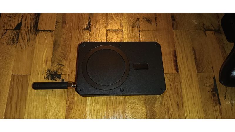
6 Threaded insers M2 4x4mm
6 4-6mm M2 Screws
Toggle Switch
Magsafe Magnet Sticker
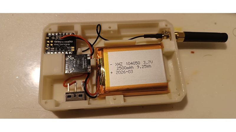
the Battery i used is a LiPo measuring about 55x40x10mm
the swith casing is about 13x7x7mm (excluding the switchy bit and the Pins)
and the flattened Xaio NRF52 is just below 12mm tall for me. including some space for the battery and Antenna cable coming off of it
I'm also using a dedicated USB-C charging board because it can charge the LiPo a little faster than whatever the NRF is doing.
the Battery is wired to the charging PCBs battery pads
the Chargers negative out is connected directly to the NRFs negative battery Pad and the chargers positive out is connected to the NRFs positive battery Pad via the power switch.
threaded inserts:
they are heat set ones
but seeing as i only have a Resin Printer because my main thing to print are minis and such for TTRPGs im using a press-fit design where i push them into their designated holes from the side and then just dripping a little bit of CA glue in there
in this Design i used 6 Inserts as well as the corresponding 6 M2 screws
i used 6mm ones. longer wouldn't fit but down to 4mm length should be fine
Regarding the Flattening of the NRF- device:
i have found that it is doable using just flush cutters, a soldering iron and one of those cheap solder suckers
for ease of reading lets call the PCB normally on top, the one with the USB-C Port PCB1
and the other one, the one with the little Antenna-connector PCB2
what i did was clip apart the female connectors on PCB2 and the plastic connecting the pins on PCB1
you can just clip in between each Pin and it becomes real easy to just pull them off each pin one at a time.
then i de-soldered the Pins on PCB1 one by one and used a solder sucker to clear the holes.
next I stuck 4 of the clipped bits from the Male connector on the Pins protruding from the bottom of PCB2 as spacers and stuck that on top of the now pinless PCB1. the pins on the bottom of PCB2 are just long enough to reach into the holes on PCB1
to avoid shorts its probably a good idea to put a piece of Kepton tape or something similar between the two PCBs
then i just flooded the holes on PCB1 with solder again and clipped of the metal parts of the female connector up on top of PCB2