Desktop nema17 robot (not finished)
Description
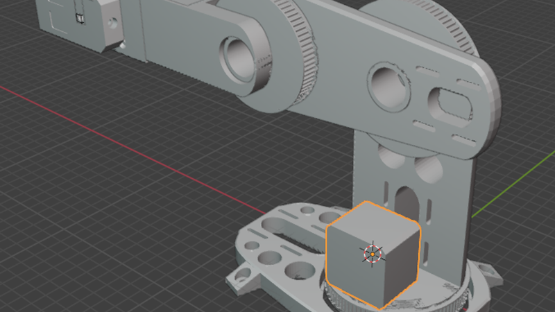
Desktop Articulated Robot Arm (NEMA 17 Edition)
> ⚠️ PROJECT STATUS: Work in Progress / Unfinished Design (Axis 1 & 2 Only)
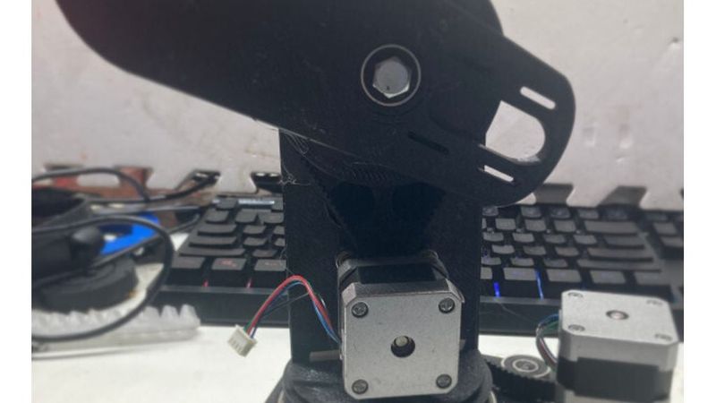
> Please note that this project is currently an unfinished design. At this stage, only Axis 1 (the base rotation) and Axis 2 (the first shoulder joint) are fully modeled and completed. The remaining axes are still in development.
>
> Design Note: This robot arm was entirely modeled using Blender. Because it was built in a mesh-based environment rather than traditional parametric CAD software, tolerances for the 95mm bearing seats and NEMA 17 motor mounts may require minor sanding, filing, or slight scaling adjustments depending on your 3D printer's calibration. Community feedback, remixes, and ideas for completing the upper links are highly welcome!
Description
This project is an open-source, desktop articulated robot arm designed for builders, makers, and robotics enthusiasts. Engineered around standard, highly reliable NEMA 17 stepper motors, this arm strikes an ideal balance between high torque, accuracy, and budget-friendly components.
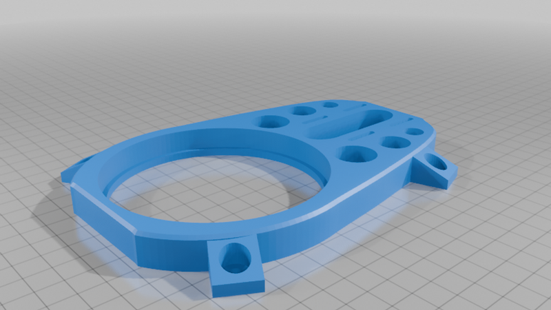
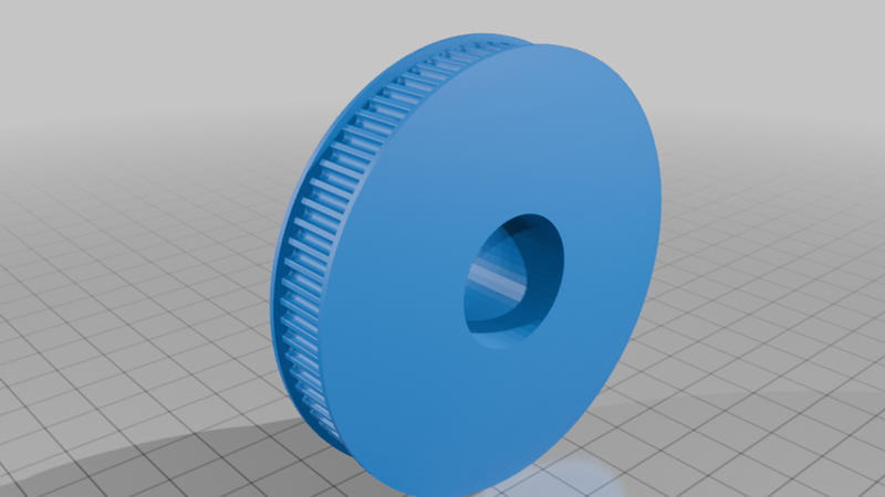
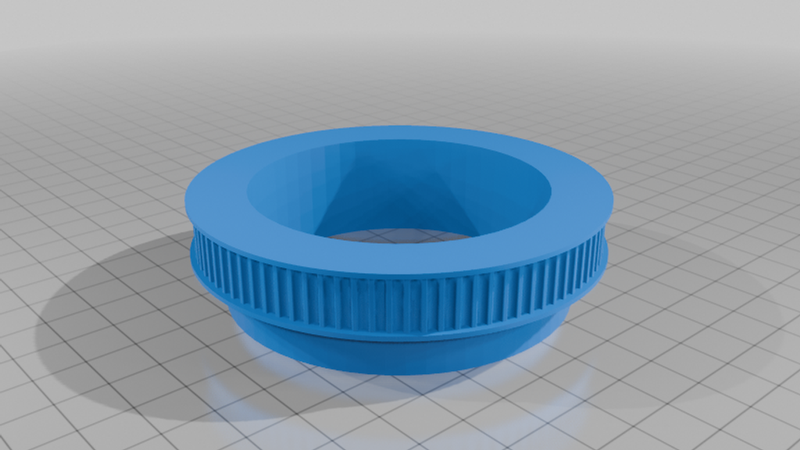
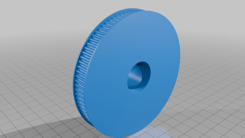
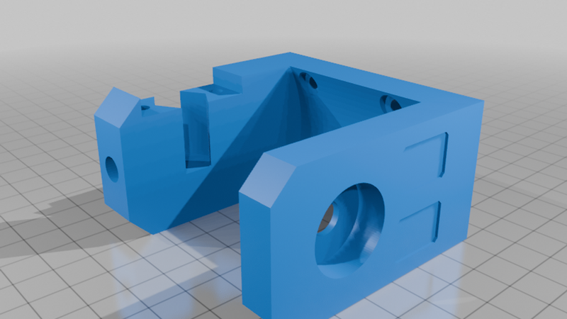
The completed structural architecture utilizes a robust 95mm rotary bearing at Axis 1 to handle heavy axial load distribution and eliminate mechanical play or wobble during dynamic movements. Motion transmission is driven by high-efficiency GT3 open-loop timing belts, offering higher load capabilities and reduced backlash compared to standard GT2 alternatives. The entire assembly is rigidly secured using a uniform hardware ecosystem of 3mm bolts (M3) and 3mm standoffs, making assembly and customization clean and straightforward.
Technical Specifications & Features
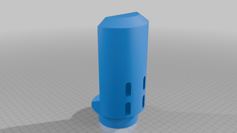
- Actuators: NEMA 17 Stepper Motors (recommended holding torque: 40 N·cm or higher)
- Primary Axis Stabilization: 95mm Heavy-Duty Ball Bearing Turntable
- Drive System: GT3 Open-Loop Timing Belts & Pulleys for high torque transfer
- Hardware Profile: Metric M3 standard fasteners throughout
- Current Completion: Axis 1 (Base) and Axis 2 (Shoulder) functional models only
Required Parts List (BOM)
1. Motion & Actuation
| Part Name | Specifications / Description | Quantity | Notes |
| :--- | :--- | :---: | :--- |
| NEMA 17 Stepper Motor | Standard 42mm stepper motors (1.8° or 0.9° step angle) | 2 | Currently required for the completed Axis 1 and Axis 2 modules. |
| 95mm Bearing | Slewing ring / turntable ball bearing (95mm outer/inner boundary specification) | 1 | Used at the Axis 1 base to stabilize rotation and handle moment loads. |
| GT3 Open-Loop Belt | 3mm pitch timing belt, reinforced | Variable | Cut to length based on Axis 1 & 2 link configurations. |
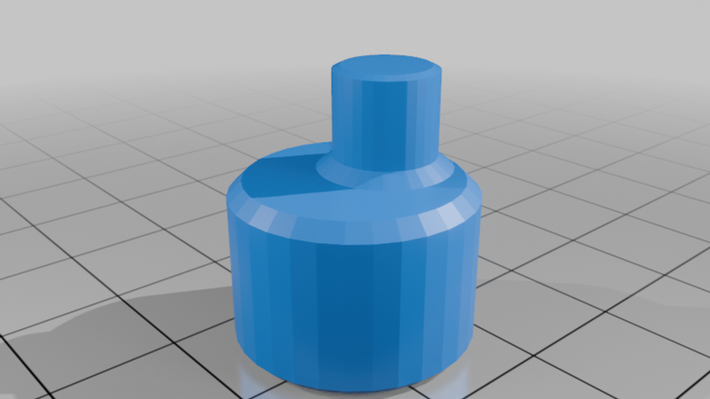
| GT3 Drive Pulleys | Matching GT3 pitch pulleys for NEMA 17 motor shafts (5mm bore) | 2 | Choose teeth count (e.g., 16T or 20T) based on your target gear ratio. |
2. Fasteners & Hardware
| Part Name | Specifications / Description | Quantity | Notes |
| :--- | :--- | :---: | :--- |
| 3mm Bolts (M3) | Button head or socket head cap screws (various lengths: 8mm to 25mm) | 1 Pack | Standardized across all structural clamping points and motor mounts. |
| 3mm Standoffs | M3 threaded spacers (male-female / female-female brass or aluminum) | 1 Pack | Used for clear electronic board spacing and multi-plate structural offsetting. |
| M3 Hex Nuts | Standard metric M3 nuts / nylon lock nuts | As needed | Lock nuts are highly recommended for high-vibration joint sections. |
3. Electronics & Control (Recommended Framework)
| Part Name | Specifications / Description | Quantity | Notes |
| :--- | :--- | :---: | :--- |
| Controller Board | Arduino Mega with RAMPS 1.4, CNC Shield, or dedicated ESP32/STM32 board | 1 | Needs to support the required number of stepper motor drivers. |
| Stepper Drivers | A4988, DRV8825, or TMC2209 (SilentStepStick) | 2 | TMC2209 drivers are recommended for smoother and quieter motion. |
| Power Supply | 12V or 24V DC Power Supply (Minimum 5A) | 1 | 24V provides optimal torque performance for NEMA 17 motors at higher speeds. |
3D Printing Guidelines
- Material: PETG or ABS/ASA are highly recommended for the load-bearing joints, motor brackets, and base plate due to their mechanical strength and thermal resistance against motor heat. PLA can be used for non-structural cosmetic covers.
- Infill: Minimum 30% to 50% gyroid or grid infill for structural parts.
- Wall Line Count: 4 to 5 perimeters to ensure structural rigidity around bolt holes and bearing seats.
Assembly & Configuration Tips
1. Base Axis Assembly: Fit the 95mm bearing snugly into the printed base housing. Secure it tightly using the M3 bolts. Ensure rotation is smooth before mounting the Axis 2 components.
2. Belt Tensioning: When running the GT3 open-loop belt on Axis 1 and 2, ensure there is a mechanism to lock and tension the belt tightly. Loose belts will introduce backlash and degrade accuracy.
3. Standoff Placement: Use the 3mm standoffs to mount the steppers