Spiderbot – 3D Printed Quadruped Robot
Description
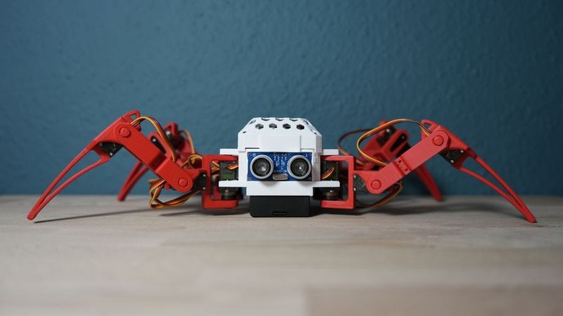
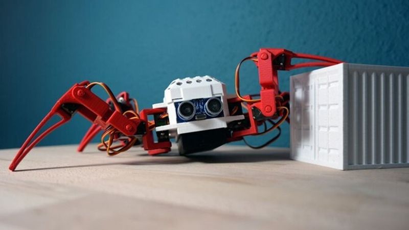
This project is a compact 3D-printed quadruped robot designed as a demonstrator for robotics, 3D printing and embedded control. The Spiderbot uses four articulated legs with a total of 12 servo motors and can be controlled by an ESP32 or a similar microcontroller platform.
I designed this robot as an exhibition attraction for IPH. The original concept was designed by Regishsu. Since we had additional requirements, such as easy handling of the components, fast maintenance, enough internal space and the integration of different sensors and modules, I redesigned the robot from the ground up.
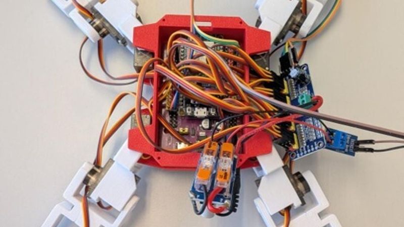
To avoid the need for a custom PCB and to make the project easily accessible for other makers, the entire robot was designed around standard off-the-shelf components. Further information about the assembly process and the required components is available in the included PDF instructions in German and English. Example code for setting up and testing the robot is also included.
Have fun building your own Spiderbot!
Features
- Fully 3D-printed robot body and leg structure
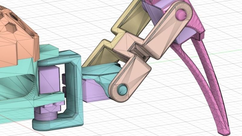
- Four legs with three degrees of freedom each
- 12 servo motors in total
- ESP32-based control
- PCA9685 servo driver for clean servo control
- Step-down module for stable servo power supply
- Optional voltage sensing for battery monitoring
- Optional ultrasonic sensor mounting position at the front
- Designed for further development and experimentation
Printed parts
You will need the following printed parts:
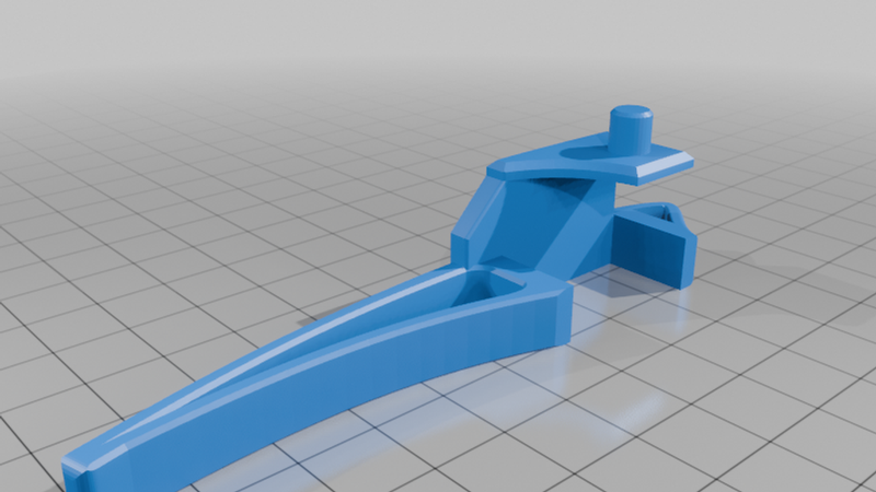
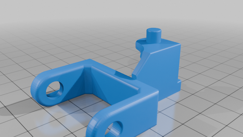
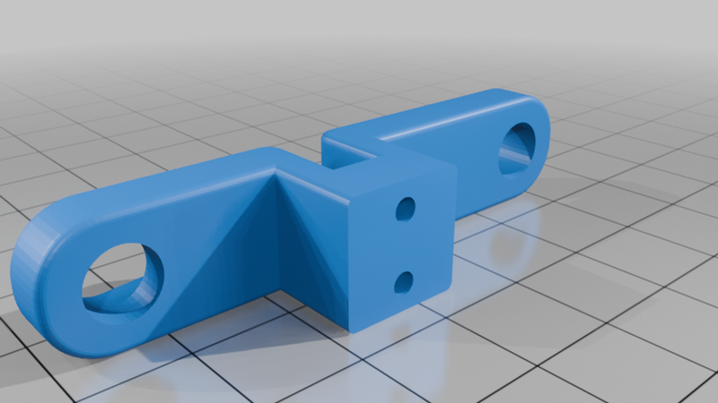
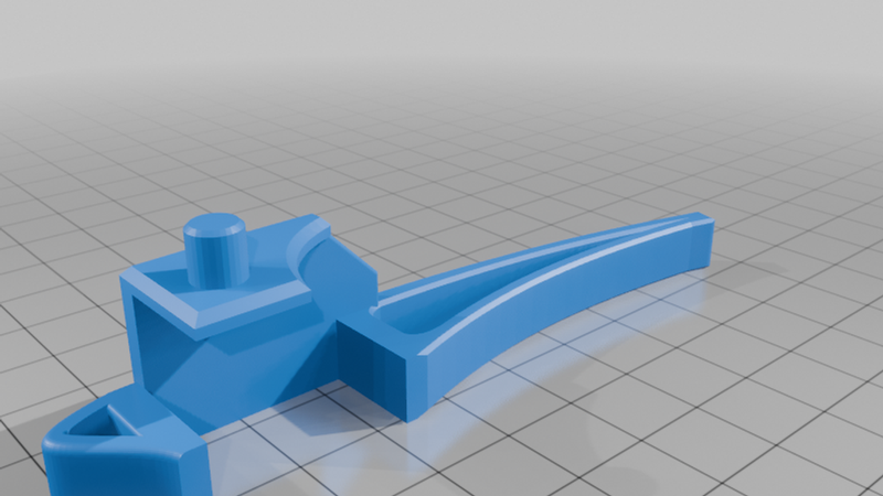
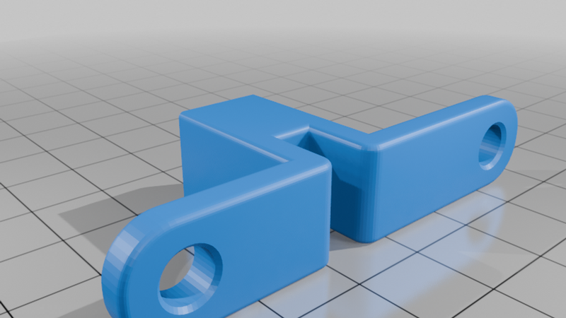
- 2x `foot_l`
- 2x `foot_r`
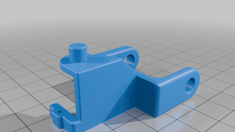
- 2x `hip_l`
- 2x `hip_r`
- 4x `joint_I`
- 4x `joint_II`
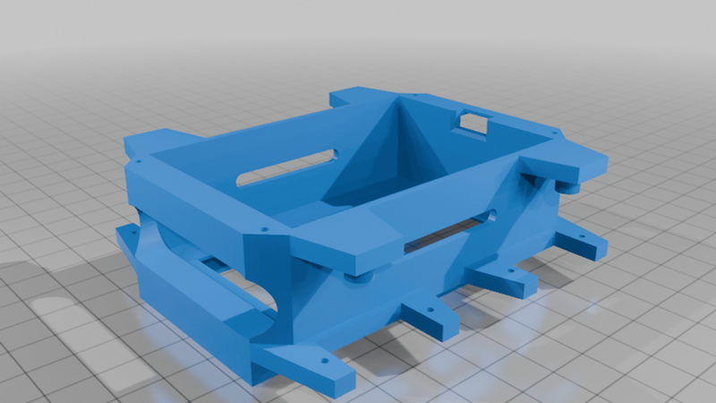
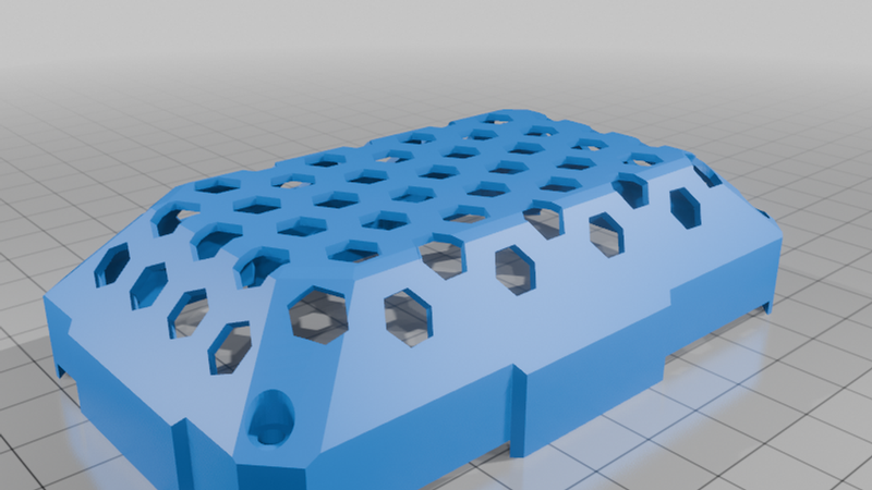
- 1x `body_base`
- 1x `body_top`
Depending on your printer calibration, some holes may need to be cleaned up or prepared with an M2 tap before assembly.
Additional components
Example electronics and hardware:
- 12x micro servo motors
- 1x ESP32 or compatible microcontroller
- 1x PCA9685 servo driver board
- 1x step-down converter adjusted to approximately 5.8 V
- 1x voltage sensor or resistor divider for battery monitoring
- 2x 18650 battery cells or another suitable power source
- M2 screws, for example M2x20 for selected joints
- Servo screws supplied with the servos
- Wires and connectors
The listed components are examples. The robot can be adapted to different control boards, batteries or sensors.
Recommended print settings
The parts were printed in PLA.
Suggested settings:
- Material: PLA or PETG
- Nozzle: 0.4 mm
- Layer height: 0.16–0.2 mm
- Walls: 3 perimeters
- Infill: 20–30 %
- Supports: only where required