FMS/Eflite Maule M7 DIY Scale Landing Gear

Description
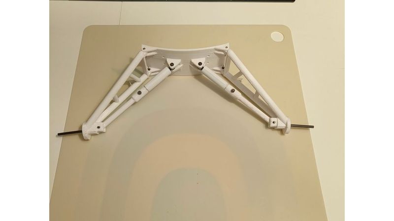
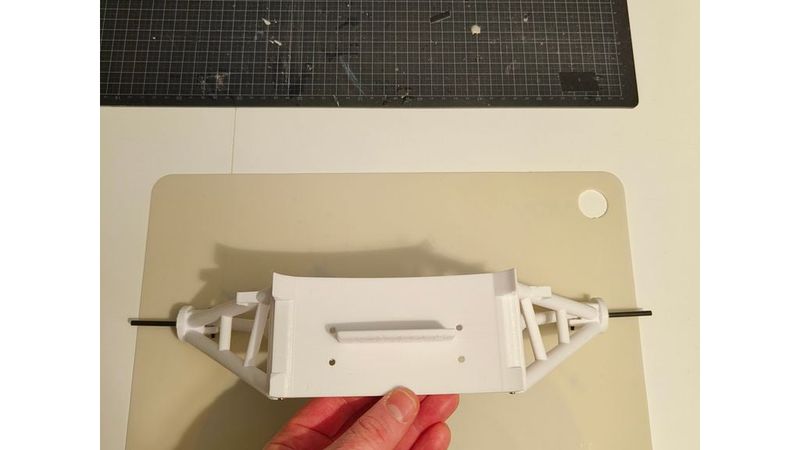
3D Printed Articulated Suspension Landing Gear for FMS & E-flite Maule M7 (1.5m)
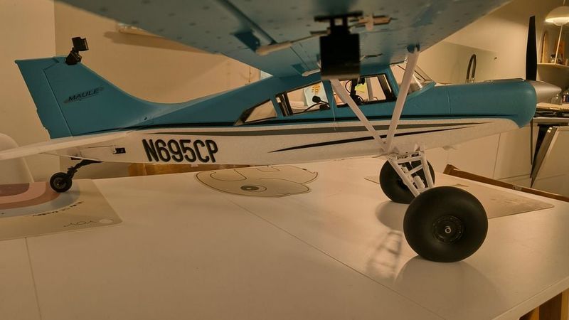
This is an upgraded, fully articulated landing gear system designed for the FMS and E-flite Maule M7 (1.5m / 1500mm).
The original factory wire landing gear is notoriously soft and bends easily. This design replaces it with a better, scale-inspired suspension system utilizing modified RC car shocks.
* Watch the Flight Tests (Snow & Grass): [https://youtu.be/90TpqiZzrnk?si=pQNEBv4N2Vp6EVFB]
* Step-by-Step Build & Assembly Guide: [https://youtu.be/SHFe8RxwEXg]
Key Features:
* Anti-Nose-Over Geometry: The gear is mounted roughly 26mm further forward compared to stock, which helps minimize the plane's natural nose-over tendency. It also slightly raises propeller clearance.
* Direct Factory Fit: Fits directly into the original factory mounting slots and screw holes. Absolutely no modifications to your Maule's fuselage are required! (Fits perfectly on both the FMS 1500mm and E-flite 1.5m versions).
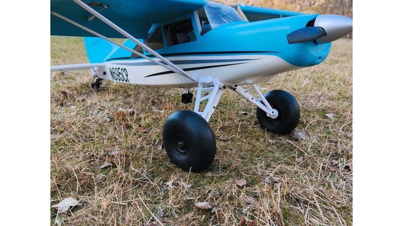
* Scale Looks, Wide Stance: Inspired by the full-scale Maule MX7 equipped with the 4" extended landing gear from the Alaska Gear Company. However, it maintains the original "wide stance" of the FMS Maule to ensure good ground handling and prevent "ground looping."
* Easy Wing Removal for Storage: The landing gear system is engineered to stay fully attached to the fuselage when you take the wings off. You can easily remove the wings for transport or storage without having to touch or disassemble the landing gear at all!
📦 Hardware & Parts Required
🔩 Required Screws & Nuts:
* 4x M3x20mm Screws: Used for mounting the new baseplate to the original Maule fuselage gear mounts. You can use the stock screws that came with the Maule, but I highly recommend getting high-quality aftermarket screws since the originals round out easily — especially if you plan to switch between floats and landing gear frequently. The plate will mount okay with the original 15mm screws, but I strongly recommend using 20mm screws since the 3D-printed baseplate is roughly 3mm thick.
* 4x M2x15mm (Minimum length) Screws & Locking Nuts: For mounting the main gear legs to the baseplate.
* 2x M3x18mm Screws & Locking Nuts: For mounting the shock absorber to the lower shock strut.
* 2x M3x25mm Screws & Locking Nuts: For mounting the shock struts to the baseplate.
Axles & Consumables:
* 4mm Carbon Fiber Rod: Cut to size depending on your chosen wheels and wheel collars.
* 5-Minute Epoxy Glue: To permanently bond the carbon fiber axles into the legs and glue the shock covers.
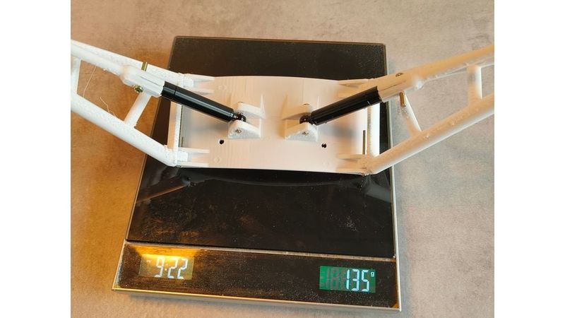
RC Shock Absorber System:
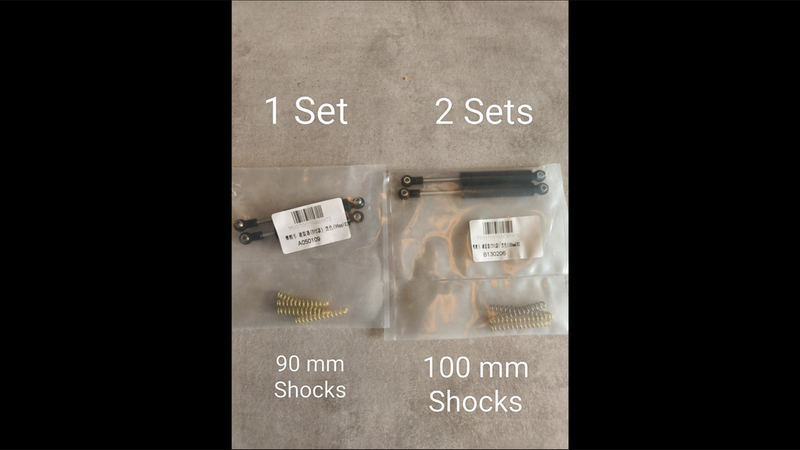
To achieve the correct retention force (roughly 3.6 to 4.5 kg per shock, measured with a fish scale), parts from two different shock lengths are combined. This acts as a reversed "bump stop" to drastically smoothen landings and prevent prop strikes. Pair this setup with low-pressure pneumatic bush tires for the ultimate scale experience!
* 1x Set of 90mm Shock Absorbers: Used for the main casings and internal rods.
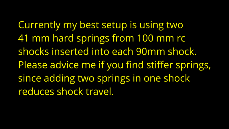
* 2x Sets of 100mm Shock Absorbers: Scavenged purely for their stiff 41mm internal springs.
Note: You will need 4 of the hardest 41mm springs in total (2 inside each 90mm shock casing). The shock struts are custom-designed around the 9mm body diameter of YeahRun shocks from AliExpress. https://www.aliexpress.com/item/1005001430624732.html?src=google&src=google&albch=shopping&acnt=615-992-9880&isdl=y&slnk=&plac=&mtctp=&albbt=Google_7_shopping&aff_platform=google&aff_short_key=_oFgTQeV&gclsrc=aw.ds&albagn=888888&ds_e_adid=&ds_e_matchtype=&ds_e_device=c&ds_e_network=x&ds_e_product_group_id=&ds_e_product_id=en1005001430624732&ds_e_product_merchant_id=106525218&ds_e_product_country=NO&ds_e_product_language=en&ds_e_product_channel=online&ds_e_product_store_id=&ds_url_v=2&albcp=22482363517&albag=&isSmbAutoCall=false&needSmbHouyi=false&traffic_server_nav=true&gad_source=1&gad_campaignid=22482362062&gbraid=0AAAAA_TvRHpAU3MAo_En-U627vO7EBIIA&gclid=CjwKCAjw-8vPBhBbEiwAoA39Wgb5qHH2aln89-4c1CgKGWixQUMIA_XDDn5CqnRfOeX1mzqAQF6LmxoC1ywQAvD_BwE
🛠️ 3D Printing Guidelines
For the best results, use your favorite PETG settings to ensure maximum strength and impact resistance. All parts were prototype-printed on a Flashforge Adventurer 5M Pro using OrcaSlicer, a textured PEI plate, and a standard 0.4mm nozzle.
Round parts can be tricky to print; if your support settings aren't right, they can wobble (causing ugly artifacts) or come loose from the bed. Since this is my first published 3D-printed project, please dial in the settings that work best for your specific machine!
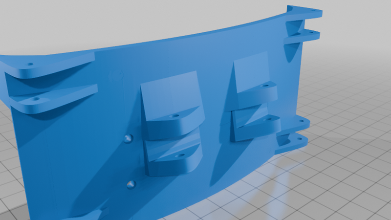
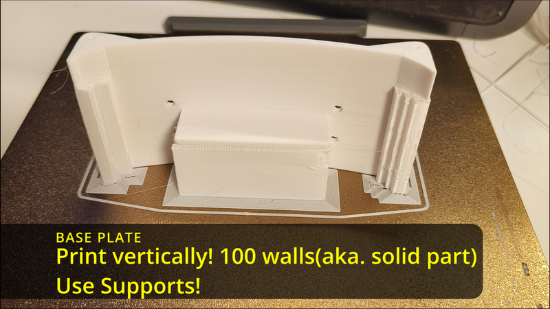
1. Base Plate
* Material: PETG
* Infill/Walls: Print with 100 walls (solid part) for maximum strength.
* Orientation: Print vertically to maximize the strength of the gear leg mounting lugs.
* Supports: Enabled.
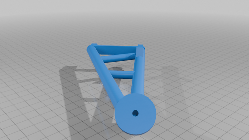
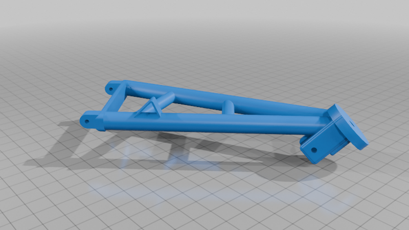
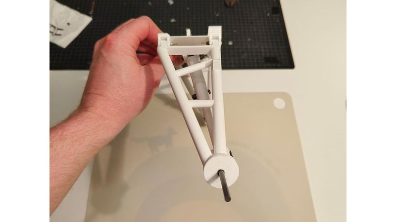
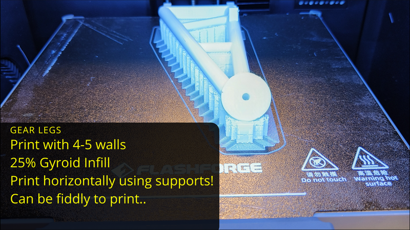
2. Gear Struts (Left & Right)
* Material: PETG
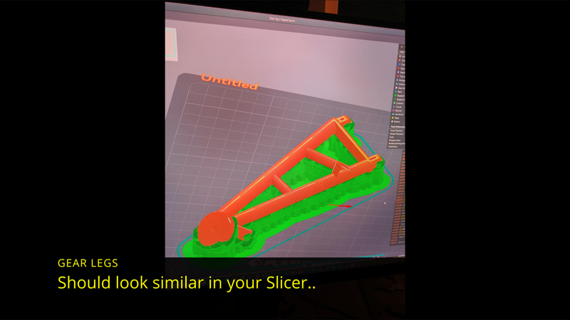
* Orientation: Print laying flat with the outside facing up for the cleanest aesthetic and optimal structural strength.
* Infill/Walls: 4-5 walls with 25% Gyroid infill to keep it strong yet lightweight.
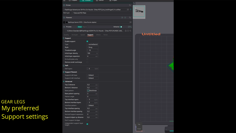
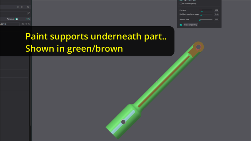
* Supports: Use "snug" supports. I highly recommend "painting" extra supports on the pointy sections closest to the print bed to prevent warping, wobbling, or ugly print artifacts on the lower gear attachment.
Note: You can simply mirror one leg in your slicer to create the opposite side. The axles are engineered with a 2-degree "toe-in" by design. This prevents the legs from spreading during forward travel and helps the gear self-correct after hard landings.*
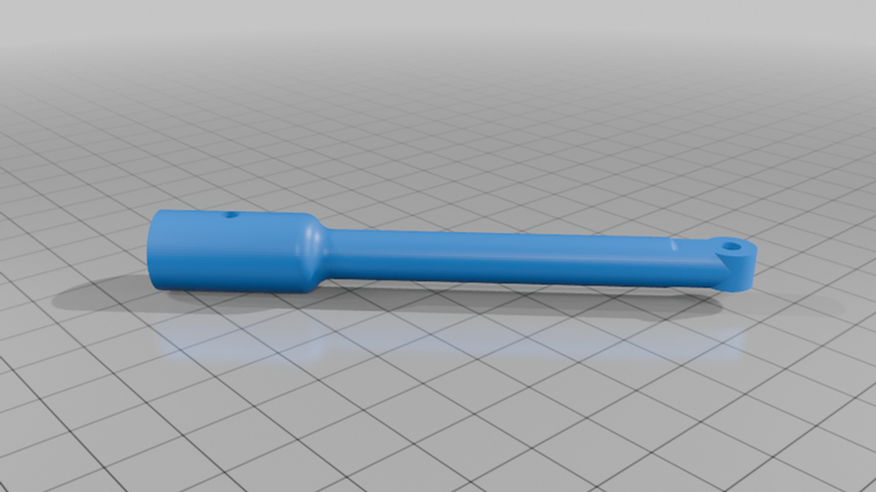
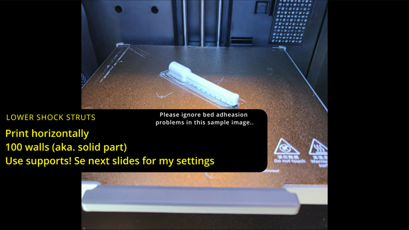
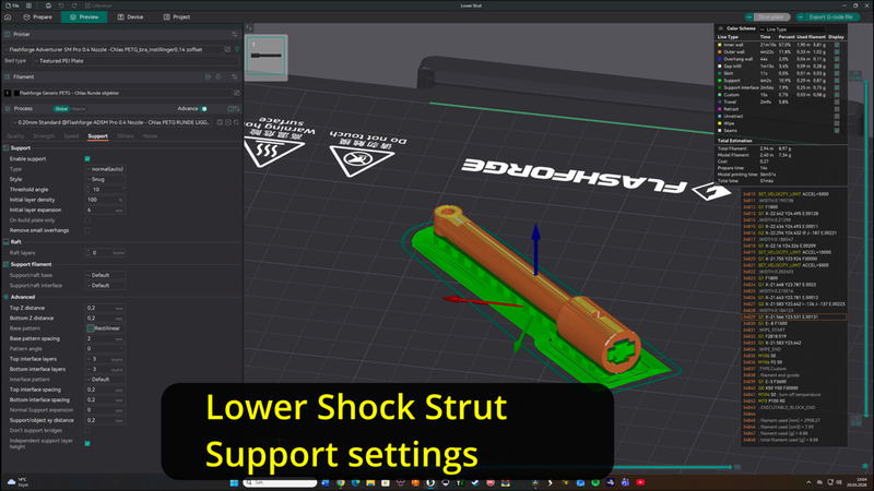
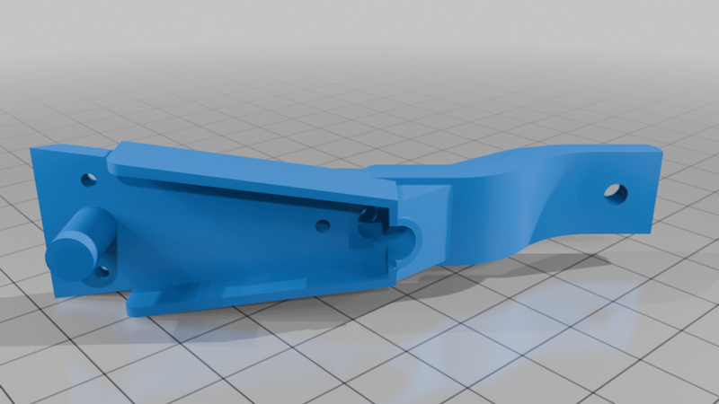
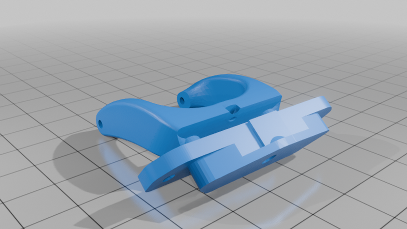
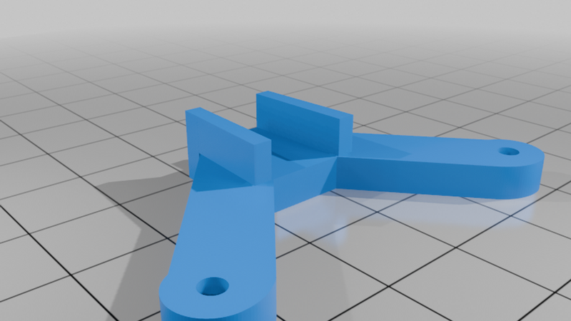
3. Lower Shock Struts (x2)
* Material: PETG
* Orientation: Print laying flat for maximum strength.
* Infill/Walls: Print with 100 walls (solid part).
* Supports: Enabled. Because this is a round part, tune your support settings carefully so it doesn't break loose. Removing supports from inside the strut where the shock inserts can be tricky; using a flathead screwdriver and twisting gently works best. DO NOT glue the strut cover on until internal supports are completely removed!
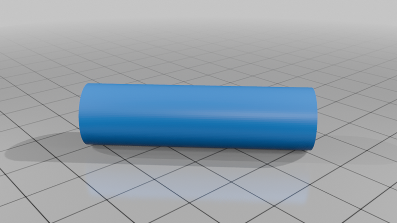
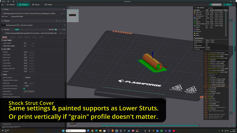
4. Shock Covers (x2)
* Material: PETG
* Orientation: Can be printed vertically (fastest) or horizontally (with supports). I printed mine laying down horizontally to match the "grain" and layer lines of the lower struts.
🔧 Step-by-Step Assembly Instructions
1. Axles: Cut your 4mm carbon fiber rods to size to accommodate your chosen wheels and wheel collars. Mix your 5-minute epoxy and glue the carbon rods securely into the axle holes on the main gear legs.
2. Gear Legs: Secure the main gear legs to the 3D-printed baseplate using 4x M2x15mm (minimum length) screws and locking nuts.
3. Shock Reversal Modification: Assemble the 9mm shocks to act as retaining/tension shocks rather than compression shocks. Remove the stock spring. Insert one of the stiff 41mm springs (from the 100mm kits) directly into the 90mm shock housing.
4. Shock Assembly: Thread the second 41mm spring onto the internal suspension rod so that the spring retainer sits behind the springs. Align the suspension rod with the spring already resting inside the 90mm housing.
5. Locking the Rod End: Using a retractable ballpoint pen (with the pen tip safely clicked inside the body), compress the springs down at the spring retainer. Vertical pressure with the pen will keep the springs compressed inside the housing so that the rod end protrudes from the housing. While holding them down, thread and screw the suspension mount/eyelet onto the rod end. Further tighten the rod end until it sits perfectly flush with the 90mm housing, then carefully release the pen pressure. Screw in the rear shock end/shock cap eyelet into the shock housing.
6. Test Fit: Do a quick test fit with the rod end of the shock to ensure it slides cleanly into the slot of the Lower Strut part.
7. WARNING: DO NOT glue on the Shock Cover part while the shock absorber is still inside the lower strut, or you risk gluing the shock shut and making it unusable!
8. Gluing Covers: Remove the RC shock absorber from the Lower Strut. Glue the Shock Cover onto the Lower Strut using epoxy. Allow it to fully dry and harden.
9. Mounting the Shock: Align the rod end of the shock absorber with the slot inside the now-assembled shock strut, inserting it rod-end first. Secure the shock absorber inside the gear strut by running an M3x18mm screw through the hole and tightening it with an M3 lock nut.
10. Baseplate Attachment: Mount the assembled shock struts to the Base Plate using M3x25mm screws and M3 locking nuts. Thread the screws in from the rear, as the angle of the holes does not allow you to insert them from the front.
11. Important: DO NOT screw the lower section of the struts to the gear legs just yet. You must mount the Base Plate to the airplane first.
12. Plane Installation: Insert the protruding lip of the 3D-printed Base Plate into the factory slot on the bottom of the Maule skids and align the holes with the plane's built-in M3 metal inserts. Secure the baseplate firmly using 4x M3x20mm screws(recommended) or the original 15mm screws.
13. Final Joints: Now, secure the lower part of the Shock Struts to the main Gear Legs using M3x22mm screws and locking nuts.
14. Wheels: Mount your preferred bush wheels and secure them with your wheel collars.
GO FLY!
Please share your printing tips or custom spring/shock setups in the comments if you find a better configuration!
Cheers!
NerdyFpv
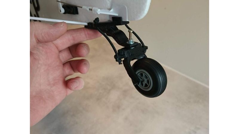
🛩️ "Baby Bushwheel" Tailwheel Modification (Optional)
I have modeled a rough "baby bushwheel" tailwheel assembly inspired by the full-scale Alaska Baby Bushwheel tail assembly to provide better tail clearance and an authentic bush-plane stance. Fits a typical 3" wheel.
⚠️ IMPORTANT STEP (Read Before Cutting):
Before mounting the new assembly, you must cut off the stock tailwheel wire completely flush with the bottom of the plane's fuselage. Do NOT cut any higher up than the bottom of the plane! Part of the internal tailwheel wire also functions as the hinge pin for the rudder. If you cut too high, your rudder will come loose!
📦 The 3 Printed Parts Included:
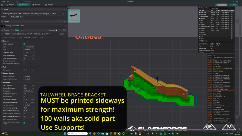
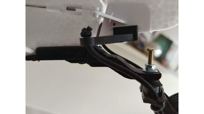
1. Tailwheel Base Bracket (Mounts to the fuselage)
This part bolts directly onto the tail of the Maule M7 using existing factory mounting points:
* Remove the screws that hold the horizontal stabilizer support struts to the fuselage.
* Align the Tailwheel Base Bracket over the frame holes and reinsert the stabilizer strut screws directly through the bracket.
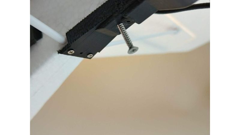
There is a 3rd mounting hole on the bracket for extra security. I highly recommend pre-drilling a tiny pilot hole through the plastic fuselage here and screwing in an M3 wood screw (or similar plastic-tapping screw) with a maximum length of 10mm to lock it safely in place. (Note: A countersunk/flathead screw is best so it sits flush, though I used a standard round-head M3x18mm screw simply because it was what I had on hand).*
Tip: You can* glue this entire bracket to the fuselage for permanent strength, but it is intentionally designed to be 100% bolt-on/off so you can easily remove it when switching back to floats!
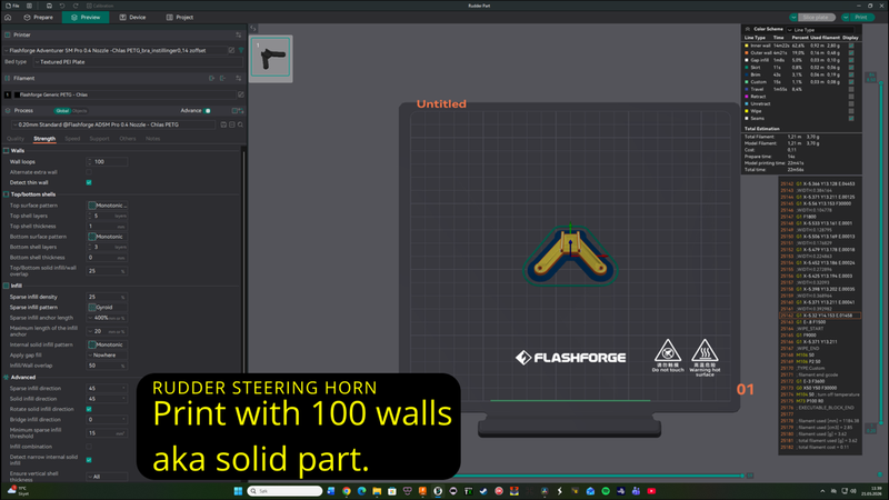
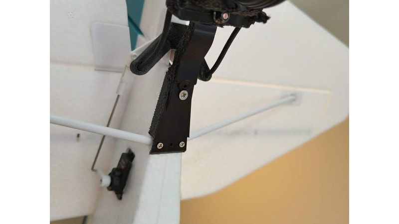
2. Rudder Steering Horns
These are the dual steering arms that stick out from each side of the tail.
* Glue this part directly onto the bottom of the rudder as shown in the photos. The part is tapered to fit the underside of the rudder. Slide into position and glue into place with Epoxy or Ca Glue.
* This allows you to run small springs or elastic cord down to the tailwheel fork. By doing this, the tailwheel steering becomes indirectly spring-linked to the rudder movement (absorbing shocks and saving your rudder servo) rather than being rigidly fixed like the stock tailwheel.
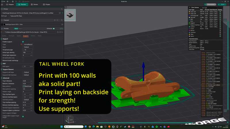
3. Tailwheel Fork
This part holds the wheel and connects to the main Base Bracket. It mounts into the main swivel hole of the mounted Base Bracket using the following hardware stack:
* Required Bolt: 1x M3 Cap Head (or Button Head) Screw with an 18mm thread length.
* Assembly Order: Run the M3 screw through a washer, then through the Tailwheel Base Bracket, then through a second washer, then straight down through the Tailwheel Fork, and finally secure it underneath with an M3 Locking Nut.
Note for Winter Flying:* My personal setup in the video uses an extra-long screw secured with a secondary locking nut above the first washer. This creates an extra attachment post where I mount a tension/retention wire for a winter tail-ski. If you are flying on wheels during non-snow seasons, a standard M3 screw with an 18mm thread length is perfectly adequate.
* Tailwheel Axle: For the tailwheel axle, I am using a custom-cut 2mm carbon fiber rod that is held securely in place purely by friction. However, you can easily add matching 2mm wheel collars if you prefer extra security. Alternatively, if you don't have a carbon rod, a long M2 screw with an M2 locking nut will work perfectly as a substitute axle.
🏷️ Credits & Remix Info
The Tailwheel Fork included in this project is a customized remix of the original design by [AKNick] on Thingiverse (Thing: #[4484038]). Thank you for the excellent base model!