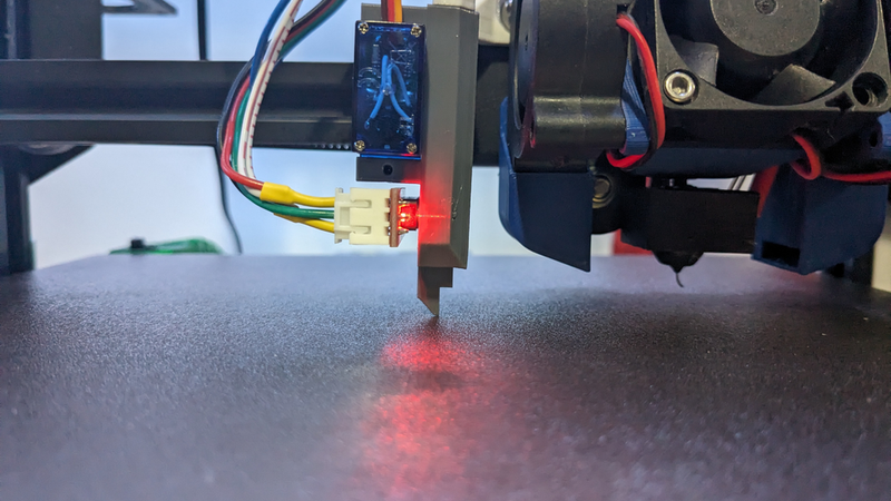
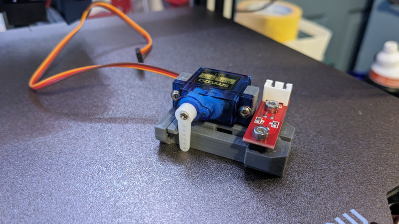
EG's Servo Probe
Description
EG's Servo Probe
This is an original design with the following goals in mind:
- Simple, easy to print parts that do not require supports or post processing.
- Non-printed parts are easy to acquire and inexpensive.
- Gravity based mechanism, no springs, magnets, etc.
- The probe can be mounted so that it is several millimeters above the bed even with Z = 0.
- Even with the above, the probe's trigger point is still multiple millimeters below the nozzle.
Materials
- 1 optical endstop/switch. I used these.
- 1 micro servo. I used these.
- The m2 mounting screws that come with the above servos.
- 2 m3 8mm long screws (attach endstop to body).
- 2 m3 10mm long screws (attach body to mount).
Printing
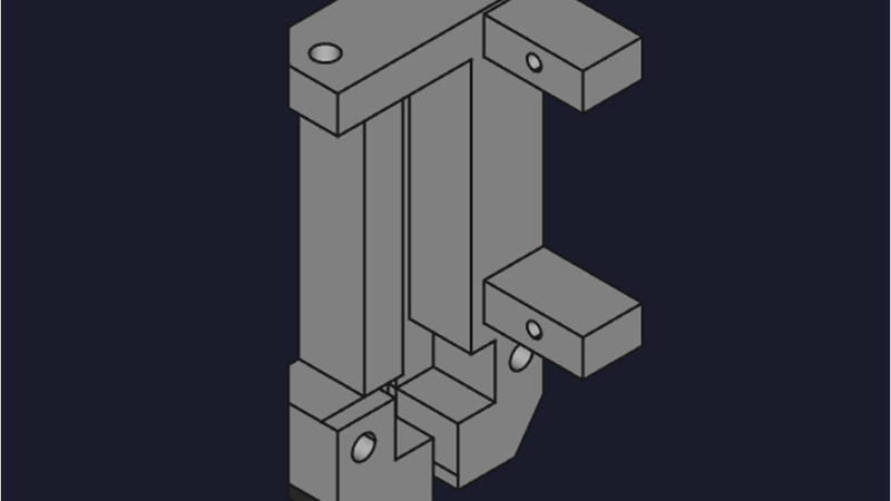
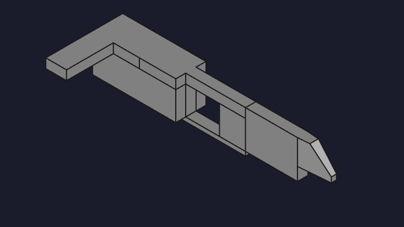
Print each part flat as shown. In the correct orientation, no supports are required.
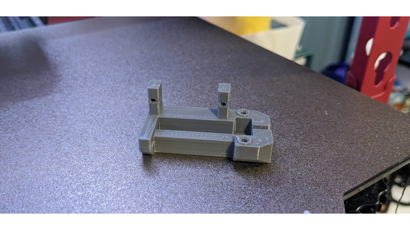
!body
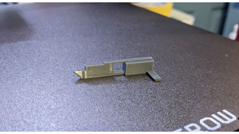
!flag
Assembly
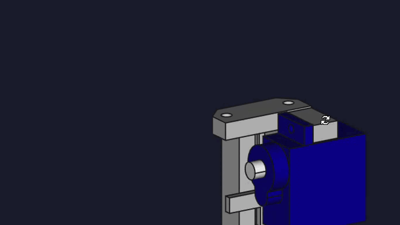
1. The flag fits into the body as shown. It should move freely.
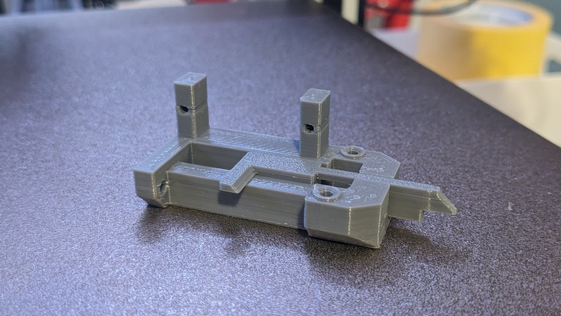
2. Attach the endstop with 2 m3 screws. The screws should be tightened until the endstop will not move at all. Verify that the flag still moves freely.
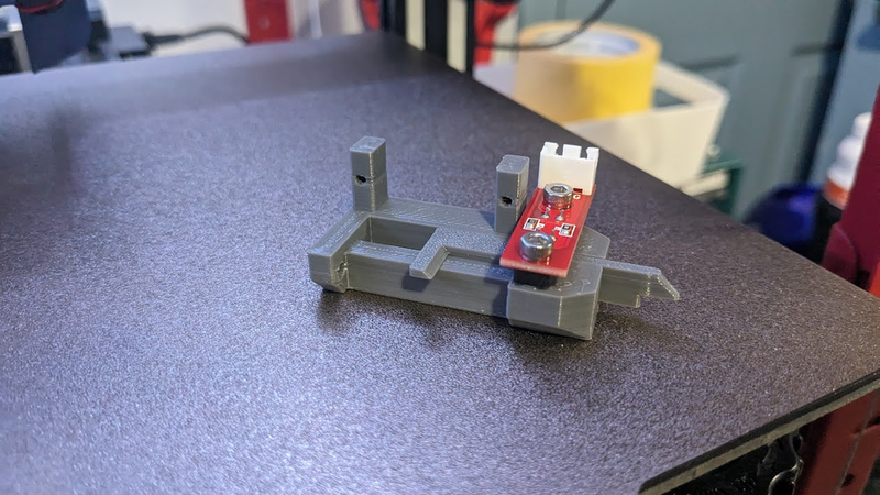
3. Attach the servo with the m2 screws that come with it. At this point, you may not know the proper orientation of the horn, so just leave it off for now. Once you have the firmware setup, you can move the servo to the proper stow or deploy position and attach the horn at that time.
Mount
The included mount should work for a generic setup on older Ender 3 style printers. You will likely want to design your own to match your hotend/fan mounts, however.
Wiring
The simplest way to wire this is to use the existing connectors on the endstop and the servo. This will vary based on your printer board, but you can either wire the endstop to your Z endstop port and the servo to the appropriate servo/probe port, or you can wire both to a dedicated probe port, in which case the endstop and servo will share 5v and ground.
In any case, verify that you are supplying 5v to the servo and an appropriate voltage to the switch. If you also supply 5v to the switch, verify the pin it is connected to is 5v tolerant (many endstop ports are not!).
Marlin Configuration
- Enable USE_PROBE_FOR_Z_HOMING.
- If the endstop is wired to the Z stop port, enable Z_MIN_PROBE_USES_Z_MIN_ENDSTOP_PIN.
- Set Z_PROBE_SERVO_NR to the appropriate value. This will be 0 in most cases.
- The deploy and stow angles should be set to 180 and 90, respectively.
- Z clearance should be at least 7 mm.
- Enable Z_SERVO_DEACTIVATE_AFTER_STOW and DEACTIVATE_SERVOS_AFTER_MOVE.
`#define USE_PROBE_FOR_Z_HOMING`
`#define Z_PROBE_SERVO_NR 0`
`#ifdef Z_PROBE_SERVO_NR`
` #define Z_SERVO_ANGLES { 180, 90 } // Z Servo Deploy and Stow angles`
` //#define Z_SERVO_MEASURE_ANGLE 45 // Use if the servo must move to a "free" position for measuring after deploy`
` //#define Z_SERVO_INTERMEDIATE_STOW // Stow the probe between points`
` #define Z_SERVO_DEACTIVATE_AFTER_STOW // Deactivate the servo when probe is stowed`
`#endif`
`#define Z_CLEARANCE_DEPLOY_PROBE 7 // (mm) Z Clearance for Deploy/Stow`
`#define Z_CLEARANCE_BETWEEN_PROBES 7 // (mm) Z Clearance between probe points`
`#define Z_CLEARANCE_MULTI_PROBE 7 // (mm) Z Clearance between multiple probes`
`#define Z_PROBE_ERROR_TOLERANCE 3 // (mm) Tolerance for early trigger (<= -probe.offset.z + ZPET)`
`#define Z_AFTER_PROBING 7 // (mm) Z position after probing is done`
`#define DEACTIVATE_SERVOS_AFTER_MOVE`
Probe Offsets
Your probe offsets will vary based on your mounting location. The following values should be a good starting point for the included mount:
`#define NOZZLE_TO_PROBE_OFFSET { -56, -18, -6.0 }`
Precision
I regularly see greater than 0.01mm precision from this probe:
`Send: M48 V4`
`Recv: M48 Z-Probe Repeatability Test`
`Recv: Positioning the probe...`
`Recv: Bed X: 115.0000 Y: 112.0000 Z: -0.0005`
`Recv: 1 of 10: z: 0.001 Mean: 0.000998 Sigma: 0.000000 Min: 0.001 Max: 0.001 Range: 0.000`
`Recv: 2 of 10: z: -0.001 Mean: 0.000248 Sigma: 0.000750 Min: -0.001 Max: 0.001 Range: 0.002`
`Recv: 3 of 10: z: -0.001 Mean: -0.000002 Sigma: 0.000707 Min: -0.001 Max: 0.001 Range: 0.002`
`Recv: 4 of 10: z: -0.001 Mean: -0.000127 Sigma: 0.000650 Min: -0.001 Max: 0.001 Range: 0.002`
`Recv: 5 of 10: z: -0.001 Mean: -0.000202 Sigma: 0.000600 Min: -0.001 Max: 0.001 Range: 0.002`
`Recv: 6 of 10: z: -0.002 Mean: -0.000419 Sigma: 0.000731 Min: -0.002 Max: 0.001 Range: 0.003`
`Recv: 7 of 10: z: -0.002 Mean: -0.000574 Sigma: 0.000776 Min: -0.002 Max: 0.001 Range: 0.003`
`Recv: 8 of 10: z: -0.002 Mean: -0.000690 Sigma: 0.000788 Min: -0.002 Max: 0.001 Range: 0.003`
`Recv: 9 of 10: z: -0.002 Mean: -0.000780 Sigma: 0.000786 Min: -0.002 Max: 0.001 Range: 0.003`
`Recv: 10 of 10: z: -0.002 Mean: -0.000852 Sigma: 0.000776 Min: -0.002 Max: 0.001 Range: 0.003`
`Recv: Finished!`
`Recv: Mean: -0.000852 Min: -0.002 Max: 0.001 Range: 0.003`
`Recv: Standard Deviation: 0.000776`
`Recv: `
`Recv: ok P63 B1`
If you are struggling to attain this, ensure that the endstop is tightened to the body properly and that the mount doesn't flex when the probe is being used. After that, verify that your printer is not suffering from Z binding. Even if your prints look fine, you may be losing a step or 2 on sudden Z movement changes and this can affect the precision by an order of magnitude or more.