Minisforum MS-01 LowProfile Double slot case with 140 mm Fan
Description
Warning! Things are not perfect yet, and this is still a work in progress. But nothing is more permanent than a temporary solution. If you know what I mean...
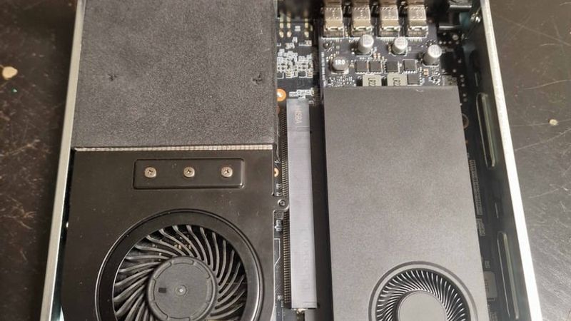
So, I became the happy owner of a Minisforum MS-01 with an Intel Core i9 and 96 GB of RAM. I’m not sure why I needed it, but I did it anyway)))
What do you do with it in your free time? Of course—you game.
A couple of hours later, I was already in a local electronics store picking up a new AMD RX-6400, and a few hours after that I had basically turned my computer into a Steam Machine.
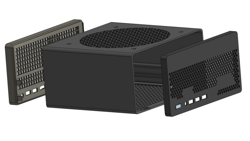
After one evening of gaming, I realized that with those temperatures my build wouldn’t last long, so I decided to make the case bigger. I couldn’t find any ready-made options, though. Well... this wasn’t my first time doing something like this. I got out my calipers and started reverse-engineering the original case. During that process I had a thought: “What if I fit a dual-slot card in here?” So I decided to design a case that could fit a dual-slot low-profile GPU and a 140x140x25 mm fan. A couple more evenings later, the design was ready. During that time, I had already swapped the AMD RX-6400 for an Nvidia RTX A1000.
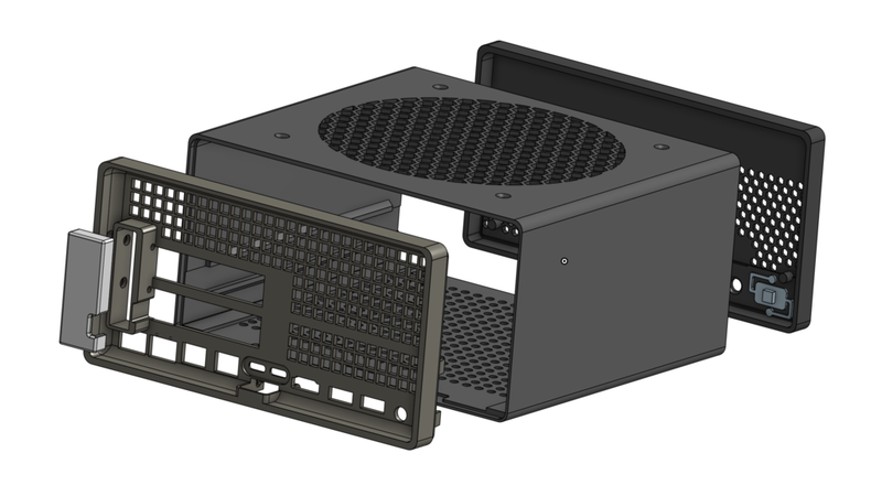
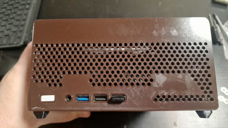
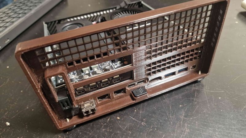
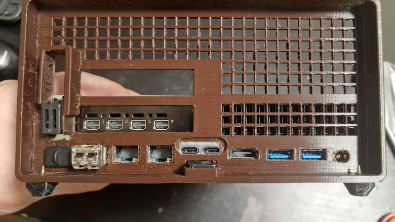
The case is designed so that the original rear panel can be removed and replaced with the custom rear panel I designed. I also included an option to relocate the latch button, but from experience—I can say it’s not necessary. The plastic holds the rear cover securely in place by friction alone.
Since I don’t have a dual-slot card, I had no way to test that setup. But if that’s your use case, keep in mind that you’ll need to cut away part of the original chassis (with side cutters) where it interferes with dual-slot GPU installation. Other than that, there should be no problems.
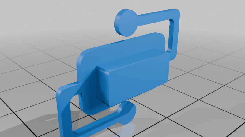
I also designed a power button so you don’t need to remove the original one from the stock case (better to keep it intact in case of resale). You only need to heat-stake round plastic pads into the body, and the button will spring exactly as it should.
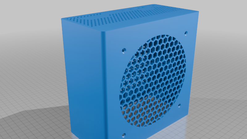
Yes, printing this beast is difficult—but it’s worth it. The front section integrated with the main body must be printed with the front face down and without supports. If you have adhesion issues, add a brim—but later you’ll have to remove it, and that may affect appearance.
The button should be oriented in the slicer with the front side facing up, while the entire underside should be supported.
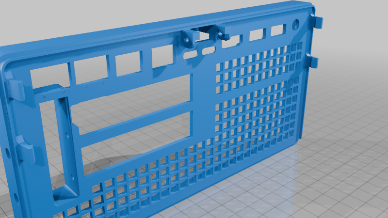
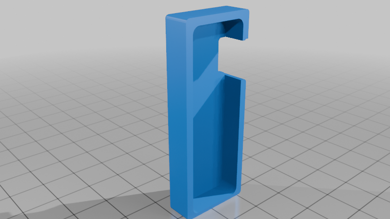
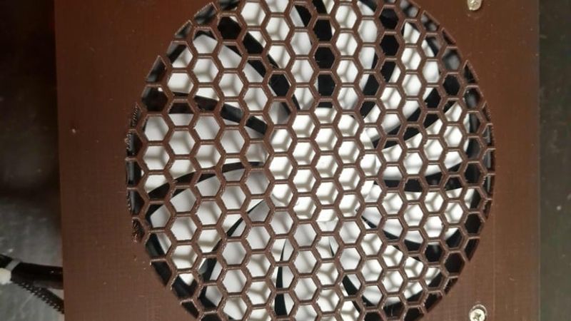
The hardest part is printing the rear panel. I only got consistent results by printing it face-down on the bed with lots of supports. But in that orientation, the latches may break (and they are important here). Another option is to print it vertically with the bottom side on the bed, add a brim, and generate supports for the latches. In that case, I would also add supports for all connector cutouts (for maximum accuracy), the wide GPU opening, and possibly the GPU bracket opening. The grille prints fine without supports—just with bridges.
If you want to close the GPU opening after installation, I designed a cover for that too—although... why? Usually no one sees the rear side anyway.
To secure the GPU, you can use the original bracket. For a dual-slot card, I’d screw everything down with self-tapping screws—I added side holes in the rear cover for that.
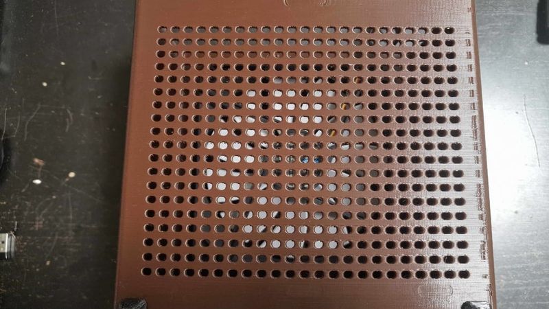
Otherwise, there should be no major issues. But this will definitely be a stress test for your printer. Especially the holes... Your extruder will be very “grateful” for the huge number of retractions.))
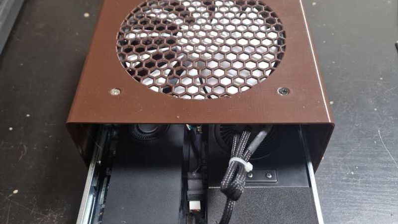
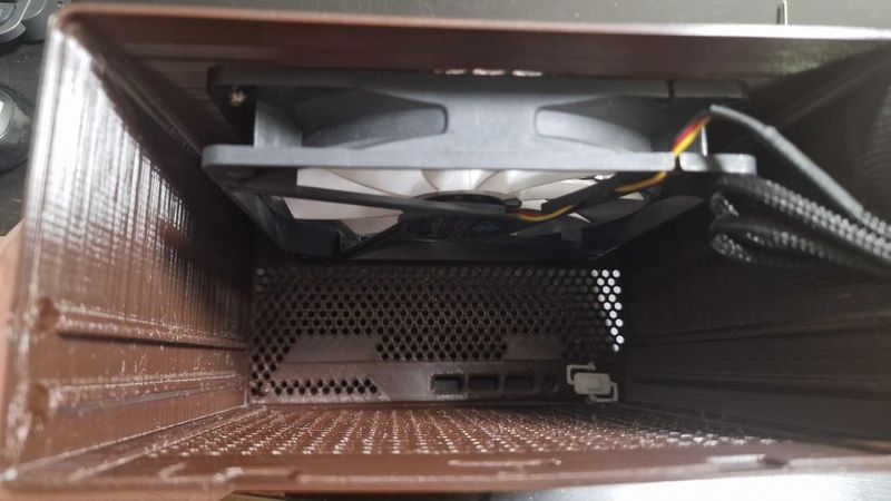
Without a 140 mm fan installed, this case will be quite flimsy, because the fan adds extra rigidity. The fan connects to an unused motherboard fan header. Access is tricky: you’ll need to fully disassemble the case and route the wires to the back side through multiple available gaps. You’ll also need an adapter from PicoBlade to a standard 4-pin fan connector. Also keep in mind that the motherboard outputs a 5 V PWM signal. If you want to run a 12 V PC fan from it, you’ll need to boost 5 V to 12 V using a DC-DC step-up converter (you do this entirely at your own risk!!!), while connecting the tachometer and PWM lines directly to the fan. In that setup, the fan can be controlled by the computer. Keep in mind the system identifies it as an SSD fan, so RPM depends on SSD area temperature. You can fix that with software in your OS for custom fan control. I went with a much simpler solution: I connected a non-PWM 12 V fan directly to the 5 V rail. That was enough for medium RPM, very quiet operation, and sufficient airflow to keep everything cool inside.
The design is not final yet, and there may still be weak spots. Feel free to message me—I’ll keep improving it.
The photos show the first experimental prototypes, so they may look rough or not very pretty. In the current design, I’ve tried to fix all the issues I found. The design is almost finished, but there’s still a lot of work to do.