Meshcore/Meshtastic Pole Enclosure and Solar panel support for Wio Tracker L1 Pro Board
Description
I have seen a solution from 'off the shelf' parts - an enclosure box with the Solar Panel supplied mount bolted directly to the lid and a commercially available vertical antenna through the top of the box and all 'U' bolted to the top of a mast. It is neat and looks like it works well.
I can't put mine at the top of the mast because I already have a 2meter antenna there, and this is cheaper to build/print than buying and assembling those components.
Also I just have a lot of fun creating stuff in blender and then making it real on the 3d printer
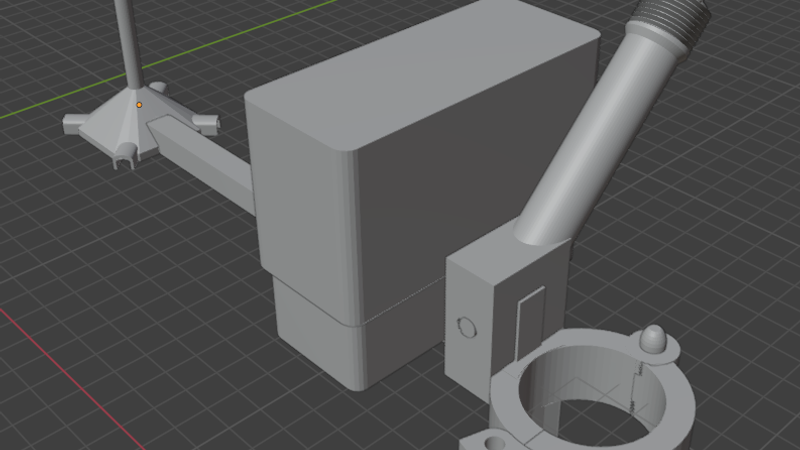
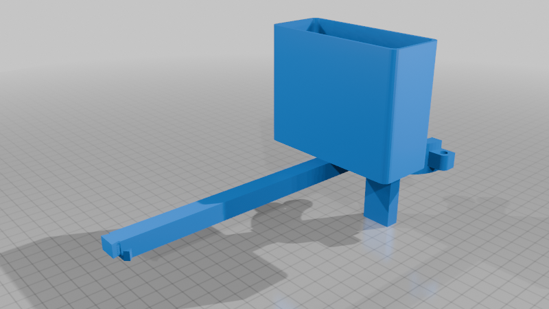
This is basically a box to contain and protect the Tracker L1 Pro from the weather, to allow it to be mounted to a mast outside.
https://www.aliexpress.com/item/1005010339711125.html
... with an arm to support an antenna and 'radome', an optional arm to mount a 3w Solar Panel
https://www.aliexpress.com/item/1005008568776761.html
... and a quick-lock clamp to secure the assembly to a 35mm Diameter Aluminium pole/mast.
This kind of evolved from being just a box zip-tied to my pole running entirely on internal battery (for a week).
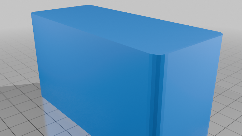
The box is a simple two-part cup-and-lid arrangement, snug fitting to secure the lid with the Meshcore device upside-down and the antenna or an antenna cable exiting a hole in the bottom. Not water-tight, but arranged such that water should not get in and if it does. it drains easily.
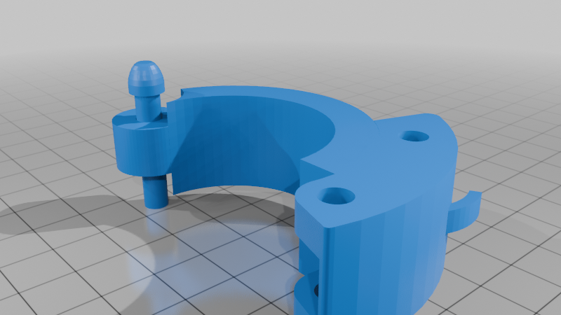
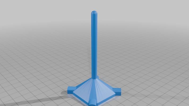
The 'Quick-Lock' pole clamp is my own design:
https://www.thingiverse.com/thing:7314134
used as a 'building block', scaled up a little here and added to make it easy to mount and dismount the assembly to the mast and to get rid of the zip-ties that perish in the sun.
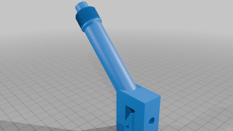
I decided to make a better antenna using an 'N'-type socket:
https://www.aliexpress.com/item/1005007059812598.html
with 4 radials from the mounting screw holes and a single radiator all made from 50amp mains cable earth, solid copper wire:
https://www.youtube.com/watch?v=JeUexihrKZQ
The 'radome' was just to stop water corroding the copper and shorting the radiator to ground.
I started out with the radials horizontal, but the SWR was terrible. I found, as in the YouTube video, bending them downward made a huge improvement, so it works out more like a dipole.
The antenna needed to be separated from the box, so I fashioned an arm for it.
Getting to the limitations of my print bed, I made the Radome/Antenna mount separate and had it clip together with the extension arm using a dove-tail joint that is held in place by the 'N'-Type socket when that is screwed to the Radome.
That worked well, but the battery kept draining so I wanted to add a solar power panel to charge the device without me having to cable it or climb a ladder every week.
So I added an arm secured with a peg near the root of the clamp that takes the screw/ball swivel joint supplied on the Solar Panel, latest version of that arm is bi-directional so it can be mounted with the antenna either side of the mast (the mast acts a bit like a reflector on a Yagi) to get the best signal from repeaters in opposite directions and still have the Solar panel pointing at the sun.
The angle of the arm is an arbitrary 45 Degrees from horizontal just to get the solar panel a bit above the radio box to shield it a bit from the midday sun.
The 53 Degrees (average) at my latitude can be set using the Solar Panel ball swivel.
The box for the radio was widened to accommodate the USB-C plug (and surplus Solar Panel wire) in the side of the radio.
Everything is printed in ASA (for UV and temperature durability) and I have included the .3mf files from the Creality Print slicer to include the suggested orientation and modifiers for support blocking and 100% infill at parts that I consider need more strength.
One thing I have found crucial when printing ASA is temperature - to have the printer enclosure sealed from all possible inward cold-air leaks/drafts, including blocking off the rear fan (not needed and should be disabled to stop it sucking cold air in from the front or lid) and holes where the rear spool holder fits. Also blocking off the gap in the door glass behind the control panel AND sealing the door hinge gap with Sellotape.
The bed is heated to 100 Degrees C and I use 280 Degees C nozzle temp.
Finally I have invested in a chamber heater and run that at 60 Degrees C prior and whilst printing.
There are also some fairly crucial speed and cooling settings that should be used (search YouTube for best ASA print settings).
Small parts and 100% infill parts require some part-fan cooling (the spike on the Radome for example) but generally if the print layer is more than 20 seconds long, you don't need fans/cooling at all.
ASA takes easily twice as long to print as PLA but results can look as good as PLA when you get it right.