ESP32 Wrover Cam Microscope (and OV3660 lens tools)
Description
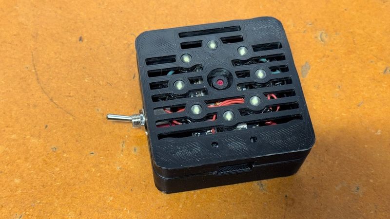
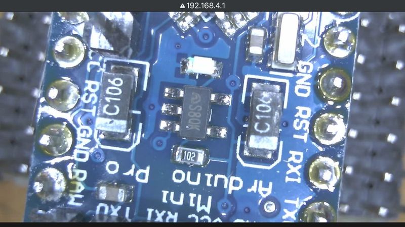
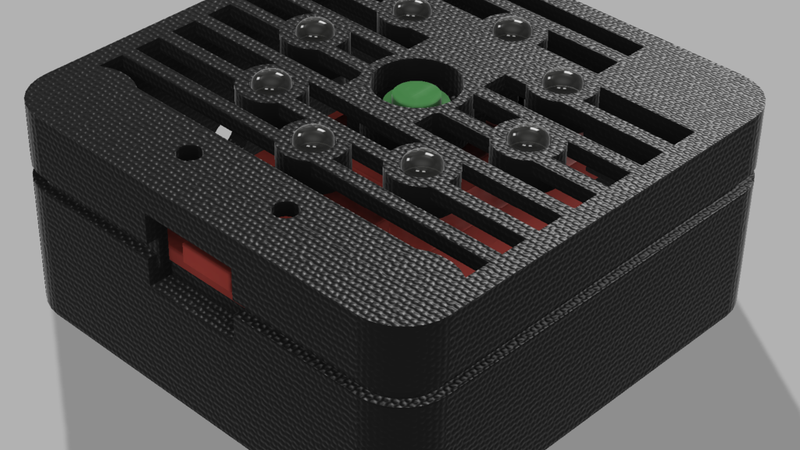
I designed this thing to use an ESP32 Wrover Cam kit as a microscope for viewing small details on circuit boards, IC's, coins, etc. It uses 8@ 5mm LEDs for illumination with an on/off switch, usb for power, and a 1/4-20 T-nut for mounting on standard tripods. The standard OV3660 camera and lens included with the ESP32 Wrover Cam kit can be refocused for "microscope applications" using the included wrench tools. I modified the "ESP32/Camera/CameraWebServer.ino" Arduino example sketch that creates an access point to view up to QXGA resolution video on any wifi enabled phone, tablet, or PC (no router required). Details on how to modify and upload the sketch to your board can be found by googling "esp32 wrover cam ap".
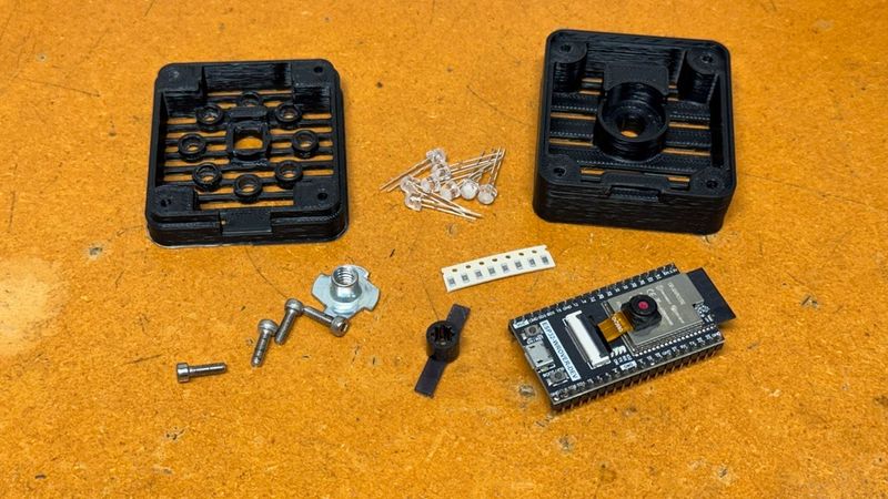
Hardware required (you'll also need hookup wire and heat shrink tubing):
1@ ESP32 Wrover Cam Kit: https://www.amazon.com/AITRIP-ESP32-WROVER-Development-Compatible-MicroPython/dp/B09ZJTVPNW
8@ 5mm "wide white" SMD LEDs: https://www.amazon.com/Transparent-Lighting-Electronics-Components-Emitting/dp/B01BUVHSSE
8@ 150ohm Resistors (1/10W also works fine): https://www.amazon.com/Chanzon-Resistor-Tolerance-Resistors-Certificated/dp/B08QR1WBPH
1@ 6mm SPST Toggle (optional... SPDT also works): https://www.amazon.com/mxuteuk-Terminal-Position-Miniature-Dashboard/dp/B07QGDDTWJ
1@ 1/4-20 tee nut: https://www.amazon.com/20-Zinc-Plated-Corrosion-Resistant-4-Pronged/dp/B0CCYQ8QBH
4@ M3-8 bolts: https://www.amazon.com/Socket-Screws-Bolts-Thread-100pcs/dp/B07CMQ1SQH
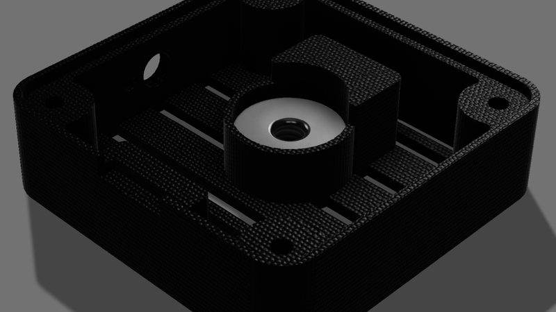
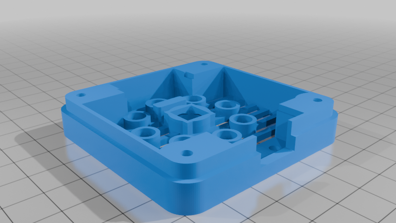
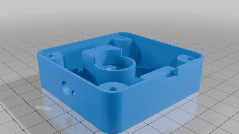
Print the case top and bottom with PETG, ABS, or similar, no rotations needed. Supports are optional; they can make the counterbored bolt holes print cleaner.
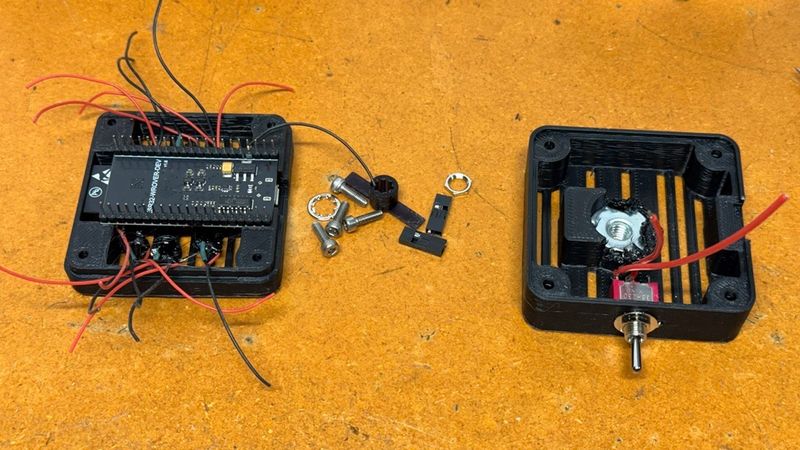
If you use a t-nut with barbs, flatten or cut off the barbs before installing it in the bottom half. I cut the barbs off, used some T-7000 to hold the t-nut in place, and a hot nail to melt the thin flange over it to prevent rotation.
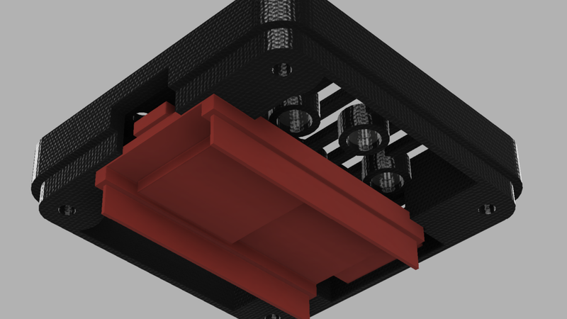
The LEDs should easily press in to place. I melted the flanges behind my LEDs and covered the rest of the rear of the LEDs with T7000 for additional security. Wire appropriate resistors to each LED and connect to the 5V (or switch if used) and GND pins on the board. There is plenty of room to use JST-XH connectors for the board connections if desired (duponts won't fit). My LED tester measured 3.00V at 18.0mA with my LEDs; I used one 150ohm 1/8W SMD resistor in series each LED. I used 0608 SMD resistors I already had on hand, but 1/4W through hole resistors should also fit. Make sure the LED leads won't make electrical contact with the board once assembled. The LEDs I used are only 5mm tall, which is shorter than standard 5mm LEDs. Longer 5mm LEDs will also work fine. I recommend lightly sanding the LED lens with some fine sandpaper (I used 600grit) to diffuse the light, which helps reduce undesireable reflections.
The holes on the side of the bottom half of the case are there for mounting a 6mm toggle switch, to turn the LEDs on/off. The switch is optional but recommended. Some very reflective subjects might blow out the camera exposure when the LEDs are turned on; in this situation turning the LEDs off and using an external lamp at a sharp angle works well.
The ESP32 Wrover board rests in the notches on the top of the case, and is held securely once the bottom half of the case is bolted on. Assemble the 2 halves of the case with 4@ M3x8 (or longer) bolts. The bolts tap directly in to the plastic.
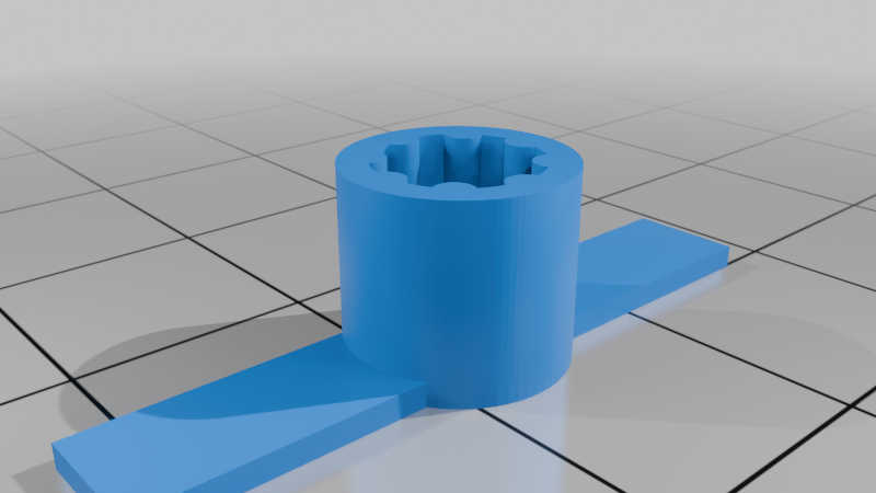
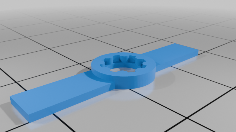
You can use this enclosure for normal infinity focus applications without any focus adjustment, but if you want to use it as a microscope you will have unscrew the lens a bit. The lens typically comes glued in place; do not brute force it with pliers or you will likely damage the lens. I uploaded ov3660 lens tools I designed based on johnyHV's tool for the OV2640 (which does not fit the OV3660 lens):
https://www.printables.com/model/877739-esp32-cam-ov2640-focus-adjustment-wrench
I recommend using johnyHV's "ov2640-holder.stl" tool, together with my "ov3660wrench8.stl" tool to help break the lens free after working on the glue with IPA and a dental pick. I printed my lens tools on an SLA printer with Siraya Tough Obsidian resin; other resins or FDM filaments may also work. The case top is designed to prevent the camera from rotating when focusing the lens; so no need to dissassemble and use the holder tool once it's installed. You will need the deep socket tool to refocus it after it is assembled in the enclosure.