Ruca. A Pico 8 hardware console.
Description
Hello!
This is one part of a project I have been working on for fun and have been sharing my progress on Reddit. For now, this resource is just for the 3D models, but once I get everything uploaded I will link to my project repository wherever that ends up being.
A little bit of explanation: I recently became interested in Pico 8 and all of the games that people have made for it. Pico 8 is a fantasy console emulator of a retro console that never existed. Pico 8 games are limited to a maximum size of 32 kilobytes and one of the most fascinating things about it is because the games are so small they can be embedded into the game artwork image file! You can check it out and read more about it at https://www.lexaloffle.com/bbs/
As my interest grew, I started programming my own games for Pico 8 and exploring all of the games others had created and shared with the community and I had a thought one day that it would be cool if I could move my favorite games to physical hardware cartridges and build some sort of a console that the games physically plugged into. After a little bit of research I found out there was a perfect 32kb EEPROM that I could read and write to with a Raspberry Pi using the I2C bus on the GPIO header. With these EEPROMs, a Raspberry Pi 3B+ and a little bit of Python code, I was able to write game roms to the EEPROM and load them into Pico 8 and run them without the need to reboot the Pi every time I wanted to switch games.
Here is the Amazon link to the EEPROM breakout boards I used for this project: https://www.amazon.com/dp/B07GMCRPSP?ref=ppx_yo2ov_dt_b_fed_asin_title
Stock on this part is very low so I am looking for an alternate place to order more of these from. I'm also hoping to develop a custom PCB that can be populated with the same parts that has a proper edge connector instead of the four solder pads that are intended for header pins.
Since I have been sharing my progress on Reddit and with friends the project has been gaining some interest, so I decided I wanted to fully document everything and make it all available online under open source with attribution license. What this means is that the whole project is free to use, modify and distribute, just don't forget my name (Please). I don't intend to gatekeep any of this and I recognize that it is all building off of the success and hard work of others, I've simply brought a few different ideas together to create something that brings me joy and want to share it with others with similar interests.
About the 3D models:
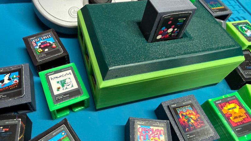
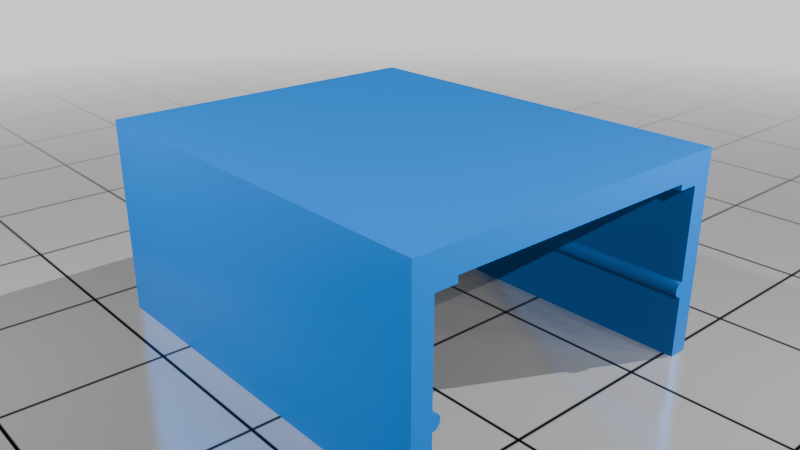
TLDR: The case is broken up into three parts so you can print each part in a different color for whatever look you want it to have. The cartridge halves are designed to lock together so no glue or hardware is needed, making it a lot easier to take back apart if you need to for some reason. There are two models for the cartridge front, one has an inset intended for the game artwork decal to sit down into.
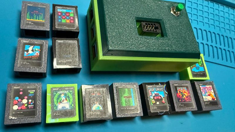
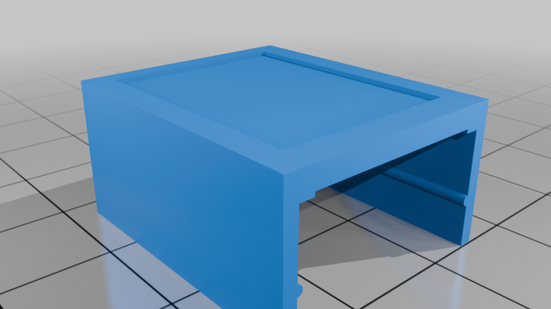
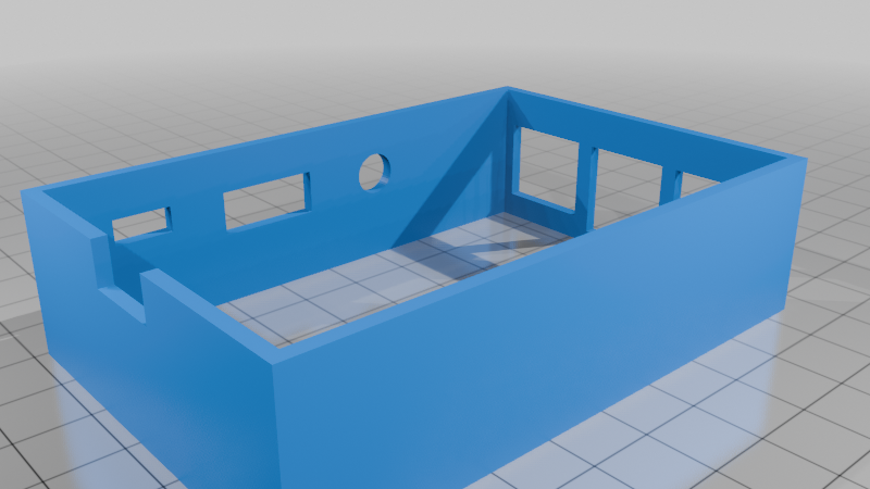
What you will find are the three pieces of a case that fits a Raspberry Pi 3B+. The top of the case has an opening for an 8 pin, 2.54mm pitch PCB edge connector. I bought this specific part on Amazon from this seller: https://www.amazon.com/dp/B0BPP6SVRD?ref=ppx_yo2ov_dt_b_fed_asin_title&th=1
The top of the case also has a round inset hole for a reset/shutdown pushbutton, Amazon link: https://www.amazon.com/dp/B0752RMB7Q?ref=ppx_yo2ov_dt_b_fed_asin_title
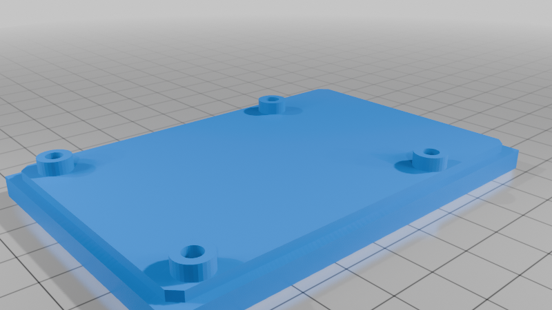
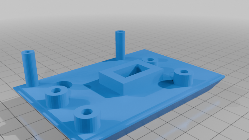
The under side of the case top has four hard mount points for M365 threaded inserts. These are typically installed using a soldering iron to heat the brass insert and press it into place. Because the 3D print partially melts during this process, I've made the mount points extra thick. I find that 3 wall layers and 3 top/bottom layers when printing with a .4mm nozzle is sufficient for this. The four mount points are to attach a GPIO proto breakout to the under side of the case lid. Here is the Amazon link to that part: amazon.com/dp/B07C54DP8T?ref=ppx_yo2ov_dt_b_fed_asin_title
The opposite edge of the lid has two taller standoffs that have holes for two M3 screws. These are just friction fit because there is not enough space around the screw holes on the Raspberry Pi board to allow for the thicker mount points to facilitate heat-set inserts.
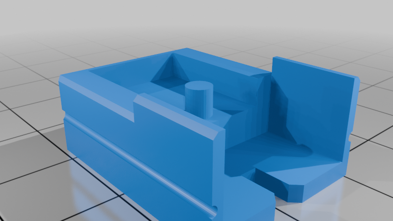
Cartridge parts: I designed the cartridge to perfectly fit the EEPROM breakouts that I was able to get and position the breakout solder pads in just the right spot in the edge connector to make the best possible electrical contact. It also helps to add a little solder to each pad to ensure good contact, but it's not a hard requirement. Just drop the EEPROM breakout in to the back piece and the peg should go through the hole in the center of the PCB holding it in place. Next, slide the top half down until it clicks into place. There are two different cartridge fronts, one with an inset for printed game artwork to sit into. Most importantly, the cartridge back has a notch in the edge that matches up with a key in the cartridge slot to make sure games cannot be plugged in backwards as this would result in 5V DC being supplied to the data lines and might damage the EEPROM.
Thanks for your interest and I hope you enjoy!