Forward facing sonar pole mount
Description
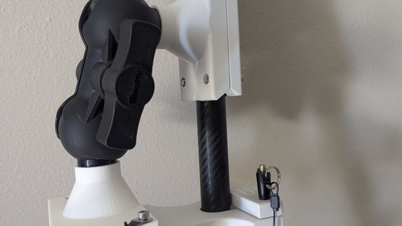
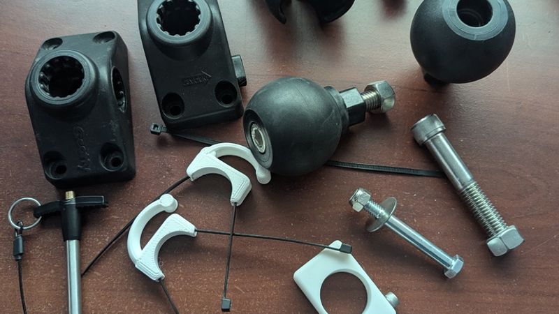
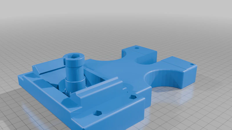
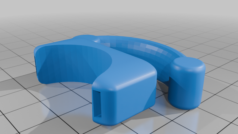
--In the first picture, all the printed components are in white.--
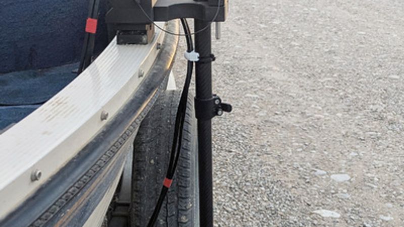
I made this forward-facing sonar pole mount to be used with a 1 1/8” (28 mm) pole (in my case a Summit carbon fiber) and the Scotty 241 and 241L rod holder bases that were already on my boat. (Why put new holes in the gunnel?) Also, because I have a portable system, I wanted to be able to move the sonar from the bow when bottom bouncing for walleye and then to the stern when using downriggers for lake trout. (Probably 70% of the time I’m fishing I point the transducer backward to watch the lures.) And, to use the system on a second old boat I have, or any boat, that has this type of base (with some limitations).
The design uses a Scotty 171 arm and two disassembled Scotty 176 (2.25”) ball bases, using only the ball, bolt, and nut. If you’re wondering why I didn’t simply model the ball in CAD, I did. The problem wasn’t making the ball—it was finding a rubberized coating that provided a reliable grip. Everything I found either didn’t hold well enough or cost more than just buying the real components. I occasionally troll at over 3 mph and in high winds so the arm’s grip on the ball is important for me. (That’s also why I went with the 2.25 ball over the 1 or 1.5.)
Printing the components:
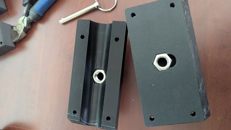
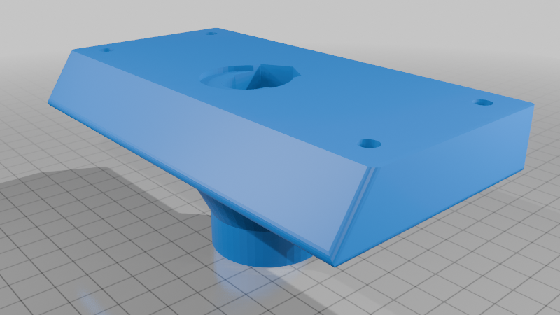
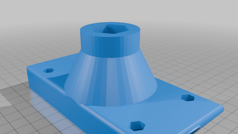
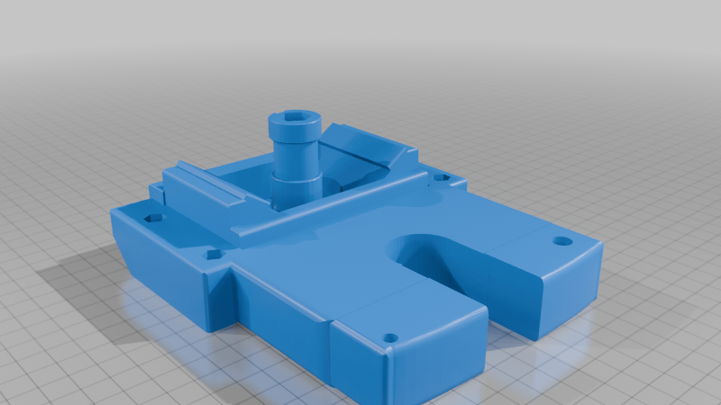
The base:
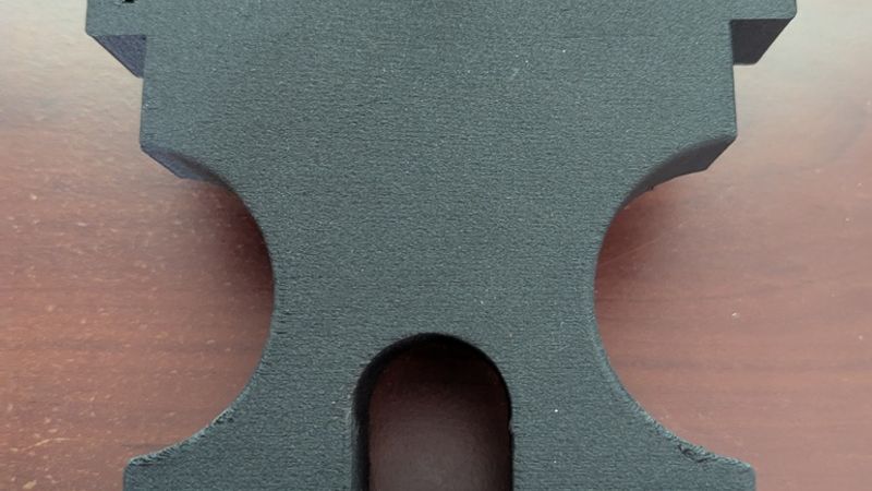
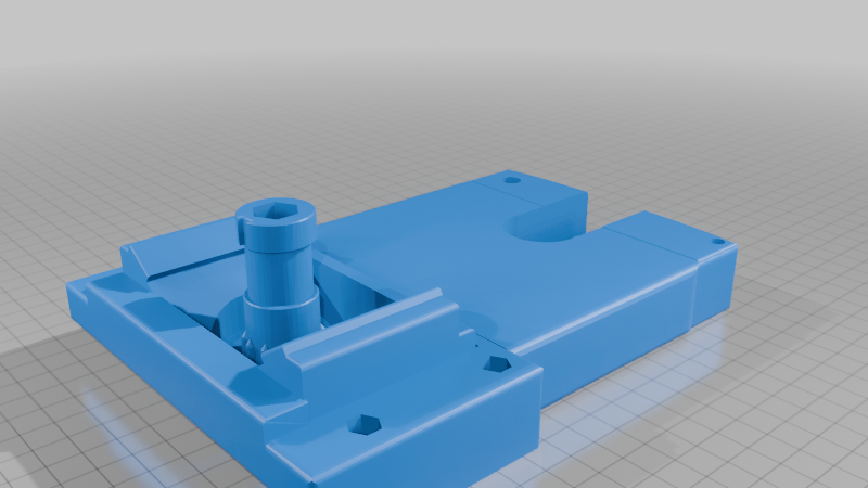
The post on the base is definitely the weakest part of all the components. -- IMPORTANT-- In the slicer, use the strength setting and lay on face on the ‘fin’ in the back so it will print at a 45-degree angle. You also need to use a modifier on the post itself. I used 20 walls. See pic. (Or, just print the whole thing with 20 walls.)
Everything else:
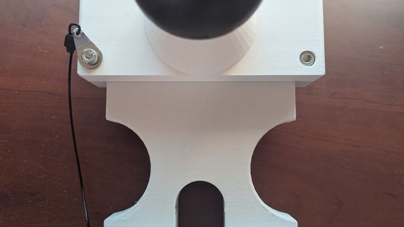
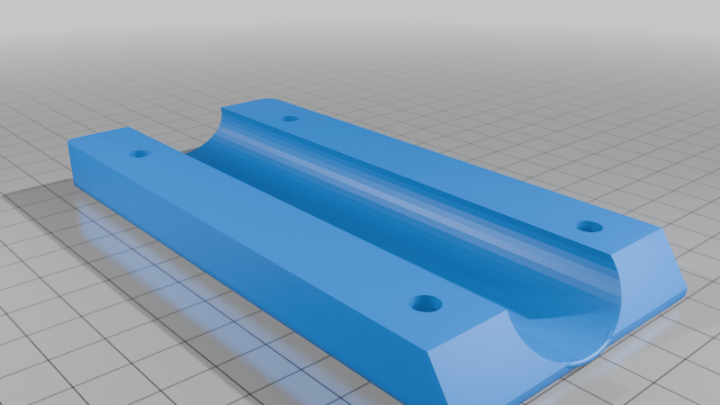
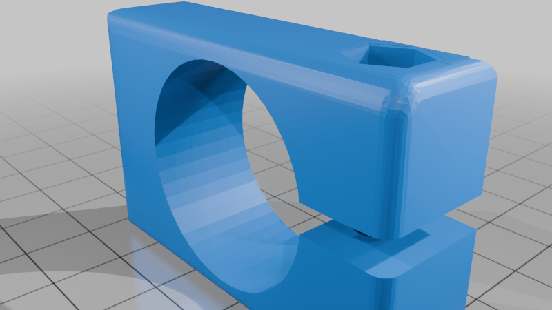
The base’s top ball mount and pole clamp ball mount (both sides) should also be printed on their fins. Printing them in this orientation increases strength and reduces—or may even eliminate—the need for supports. Use the strength setting for these parts, as well as for the rest.
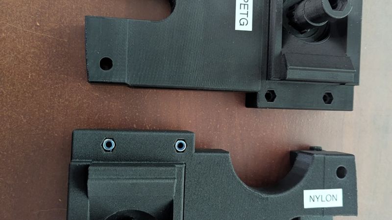
During the design process, I unintentionally broke the base and its post several… billion times. After finalizing the design, I continued with deliberate stress testing, which ultimately led to two base versions. The cutout version saves material and is best suited for PA, PC, or possibly ASA. The full-size base is recommended if printing in PETG. The PA6-GF filament I ultimately used for the base turned out to be strong enough that the carbon fiber pole failed (cracked) before the printed parts did—even when using the cutout base. All the other components I believe would be fine in PETG but I haven’t tested that.
Parts Needed:
• (10) M5 lock-nuts
• (9) 35 mm M5 machine screws (ball mounts and stop)
• (1) 45 mm M5 machine screw (gate)
• (1) 5/16” quick-release pin (3” shaft) for the gate
• (1) 5/16” hex head bolt (~2.75” long) for the post
• (1) 5/16” lock-nut and washer for the post’s bolt
• zip ties for the cable holders
• (1) 2.25” ball arm
• (2) Scotty 176 ball bases- disassembled
• Scotty 241 or 241L rod holder
________________________________________Additional Notes:
• The fit on everything is tight. Minor scaling adjustments in your slicer may be required.
• The distance from the outside edge of the 241 mounts to the outside edge of your rub rail cannot exceed ~3” unless you extend the base in CAD—after that, your limit is the arm length.
• The gate is really only necessary for higher trolling speeds and/or high winds.
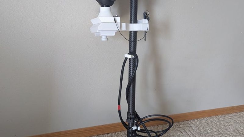
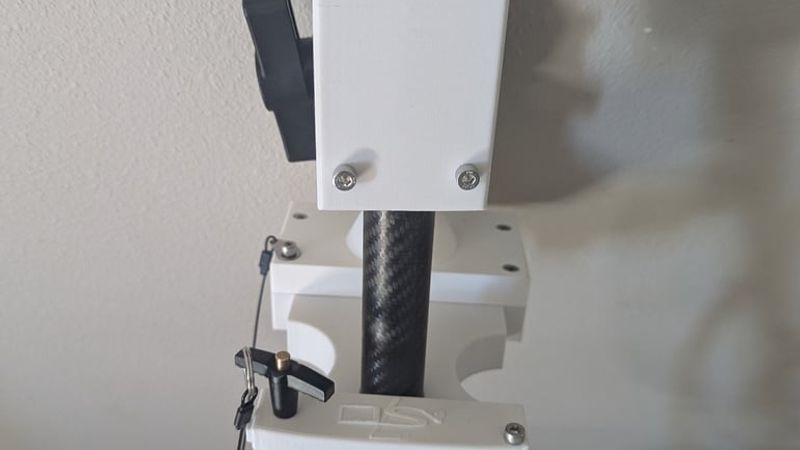
• The cable holders were designed around a Garmin LVS34 but should work with other transducers as well. Add a second zip tie below the top holder (around the shaft only, not the cable) to act as a stop to prevent it from sliding down.
• Because this was designed for my specific pole it will not work with a larger pole, for instance, 1” pvc (1.315” O.D.). I (or you) could model one that will work with other size poles.
• The nut for each ball may seem like it doesn’t fit in its slot, it does. After you get it started, tap it in until it bottoms out.
• Don’t over tighten the screws or bolts but do tighten the zip ties as much as you can.
• If you’re installing a new 241 mount specifically for this setup, if possible, try to position it so the pole rests in the base’s slot while also lightly touching the rub rail. This will create two points of contact for added stability and less stress on the post.
----My slicer said I needed supports for a lot of the prints. Ignore that liar, I didn't use them at all.
New additions and updates:
I adjusted the cable holder by thinning the inner walls slightly so it grips the pole better, and added a larger version for a more secure hold if needed. It can be a bit tricky getting the cable through the opening....printing it with the slicer’s “standard” setting makes it easier.
I also added a “shorty” base—something I should’ve included from the start but it has NOT been tested.