Knife sharpening jig/clamp v2
Description
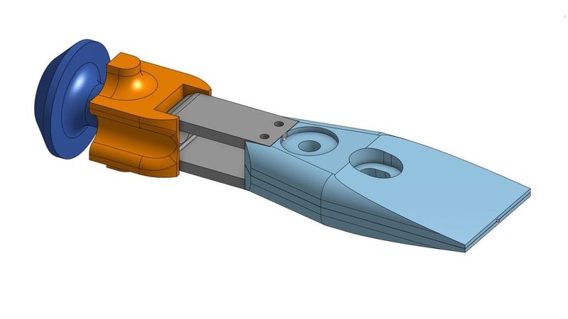
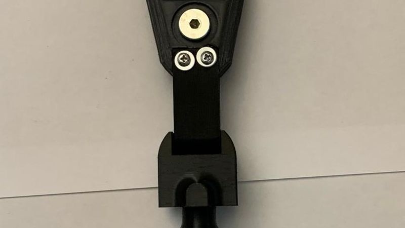
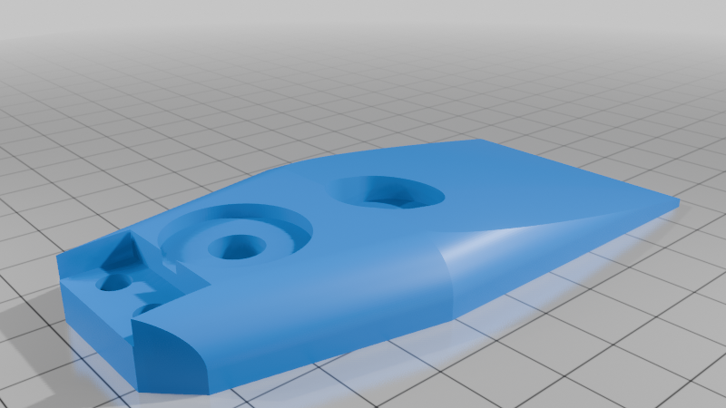
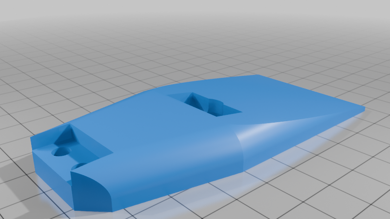
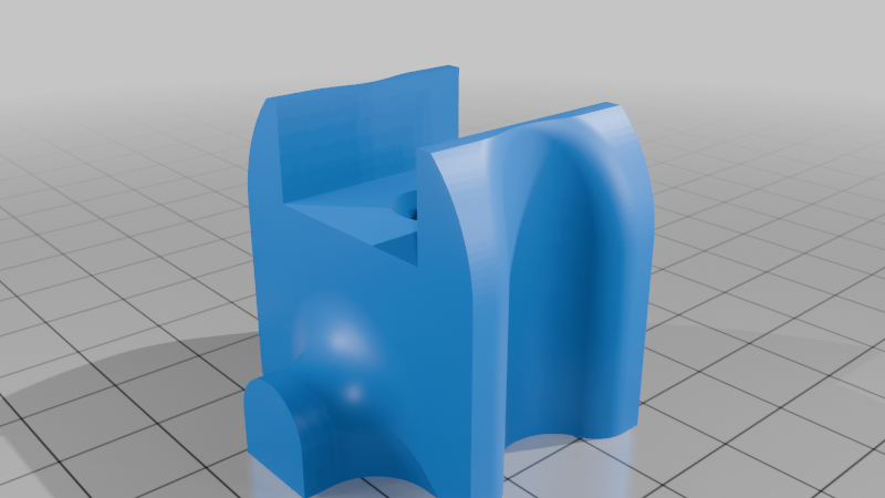
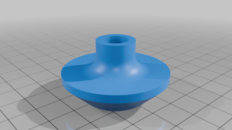
Knife Sharpening Jig v2
Self-centering with swivel and linear action.
Most dimensions can be easily adjusted in Onshape, but since this was my first Onshape project, not everything is perfectly optimized.
Does it fully replace the Tormek KJ-45 in functionality?
No. It lacks many quality-of-life improvements and the precision you'd get with a $50–80 jig.
The jaws are not made of metal. There are no springs to automatically open the jaw. The screws for clamping aren't machined to distribute clamping pressure optimally, etc.
However, you get to choose the exact size of the jaws, the length of the handle, the color of individual parts, and you can even make one for each of your knife-sharpening buddies! :D So, decide for yourself whether it's more sensible to print it or buy it from Tormek or another manufacturer.
That said, the comparison is theoretical, as I don’t own any Tormek jigs. Additionally, I don’t own a Tormek wet stone grinder, so I can’t guarantee that this jig will be compatible or fully replace any equipment.
Features
- Self-centering clamping design.
- Two handles:
- Linear handle – to move the blade parallel to the bar/rail
- Swivel handle – to swivel the blade around a fixed point
- Optimized for shallow grinding angles (≈15°)
- Uses metric hardware
- Parametric CAD for easy modification
Caveats
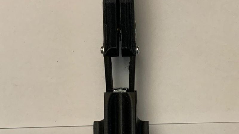
- Lacks handle length adjustment. Although the linear handle can be used with a longer reach by adding extra nuts and a longer bolt, the swivel handle is designed to interlock with the spring for precise alignment. For now, if you need to adjust the swivel point, you'll need to modify the part in your preferred software to stretch it.
- It lacks the more flexible and better looking spring from the first version. Sadly, the spring interfered with the sharpening process when using the swivel handle and prevented a bolt from being inserted during assembly. So, it’s a flat boring spring for now. :(
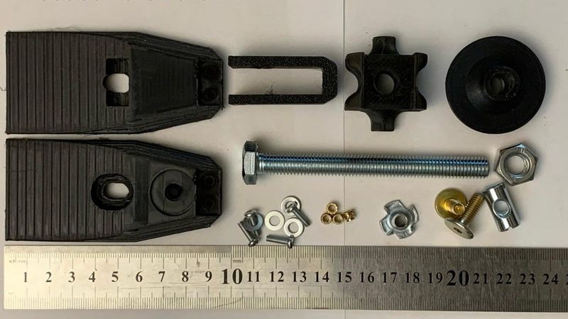
Bill of Materials (BOM)
Filament
- PLA (for rigidity)
- Plates (100% infill required)
- Handles (infill of your choice — I used 30%; can also be printed in other materials)
- PET-G (for slight flexibility)
- Spring (10 walls / 100% infill)
Hardware
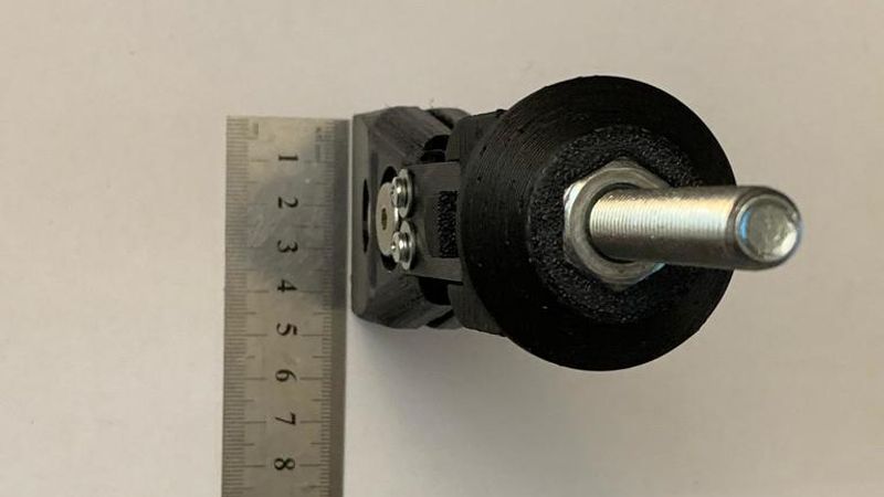
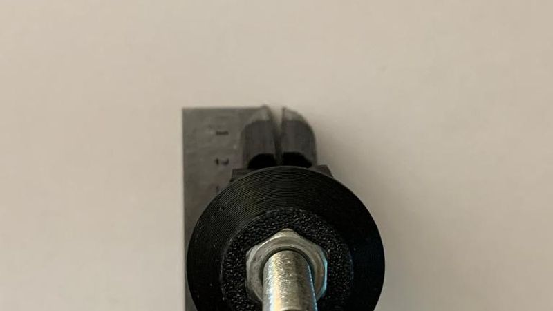
- 1× M10 bolt x 60mm (minimum)
- 1× M10 nut (embedded into the handle for the linear handle)
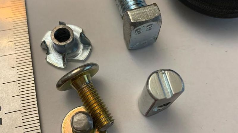
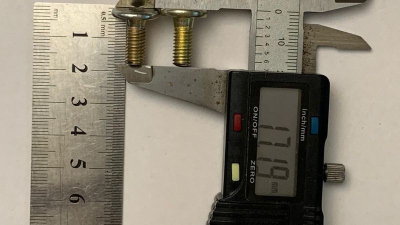
- 1× M6 flat-head furniture bolt (for clamping plates)
- Cut to length: 17-18mm
- 1× M6 prong nut (for clamping plates)
- Cut to match plate hole depth (heat-set) approx. 7mm, measuring the barrel that will be inserted
- Heat-set on the inner side of Plate A near the spring
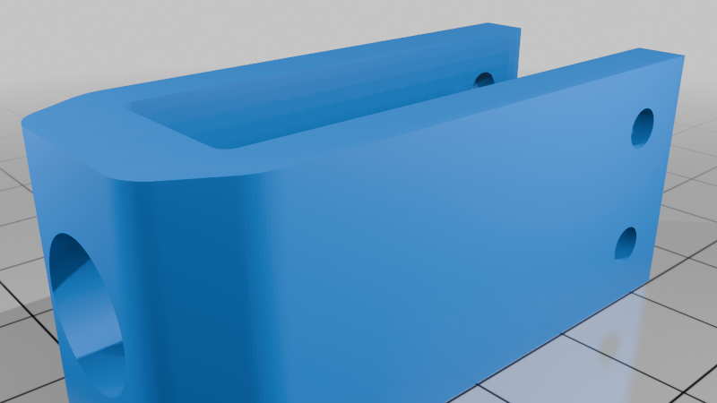
- 1× M6 x 20mm x Ø10mm Cross Dowel/Barrel Nut - Centre Threaded
- Ground down to sit flush with the clamp (Do not grind it while mounted in the knife jig; your plate will melt)
- 4× M3x10mm bolts (for mounting the spring to the plates)
- 4× M3 × 4 × 5 mm heat-set inserts
- Insulation or anti-slip tape for the jaws to help with traction
Tools Required
- Soldering iron with heat-set insert tips (or without if you’re super handy)
- Angle grinder or hand saw (for cutting bolts, prong nut, and grinding down the Cross Dowel/Barrel Nut)
- 3D printer with a heated bed (for PET-G)
- PEI build surface or generous use of glue stick (for PET-G)
- Courage — to trust the method you decide for securing the hardware before approaching it, donned in PPE, with an angle grinder roaring in your hand.
Printing Recommendations
⚠️ Important – Calibrate your flow rate before printing the plates at 100% infill. Over-extrusion at full infill will result in failed prints.
- Enable dynamic/organic supports
- Be generous with brims for plates and the handle. I used 10mm brims to avoid warping.
- Print plates at 0.3 mm layer height to reduce print time
- For plates, use Z Anti-Aliasing (ZAA) and top layer ironing for a smoother surface finish (or decrease layer height).
- ZAA may require some post-processing but can save many hours of print time.
- ZAA explanation by CNC Kitchen:
- For handles, use Variable Layer Height printing/slicing to achieve a smooth fillet. I printed with 0.3 layer height, decreasing to 0.1 for the fillet regions.
Notes Before Printing
- If a wider or narrower version of the clamp is needed, the jaw width is easily adjustable in Onshape using the first sketch of the project.
- The handles are designed for a 12 mm diameter bar/rail to slide upon. You may want to adjust the radius of Fillet1 and Fillet2 in Onshape so they match your bar/rail diameter.
- Note on rigidity: I have printed many versions of the clamp — the widest being 60mm and the narrowest 40mm. The 60mm version appears to be more rigid than the narrower ones, but it doesn’t fit all of my knives comfortably. I assume there’s a point where rigidity improvements are outweighed by the flex across the jaw, and a single bolt is no longer sufficient to keep the clamping pressure evenly distributed across the jaw. An additional bolt should be introduced in the Onshape project.
Notes on Assembly
- Please carefully review the pictures for prong nut placement. One nut is heat-set on the inner side of Plate A near the spring, and the other nut is heat-set from the outside near the jaw in Plate B.
- When heat-setting the prong nuts, I set them flush with the part rather than fully embedding them. Only the teeth are melted into the plastic.