Battery 12V Li-Ion for heavy loads

Description
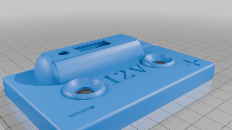
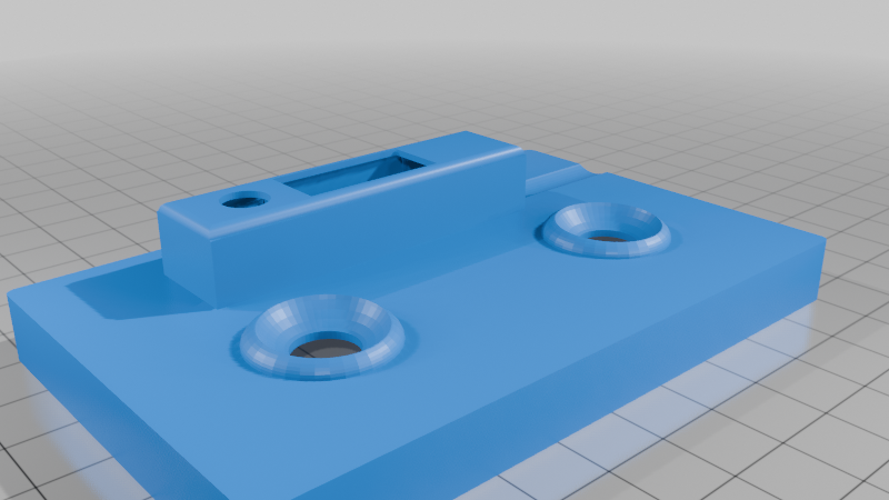
12V Battery Assembly Instructions
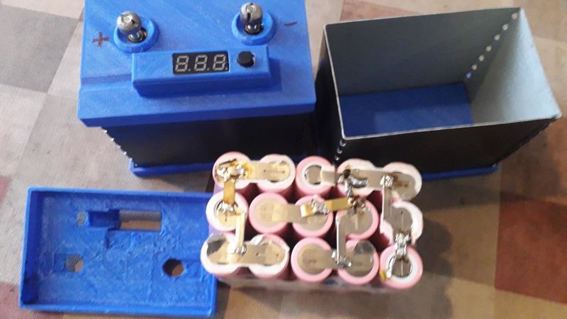
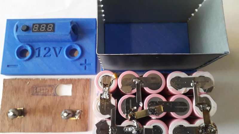
This battery is constructed from used 18650 cells, arranged in a configuration of 3 series and 5 parallel groups (3S5P). The total capacity is 10-15 Ah, depending on the specific cells used.
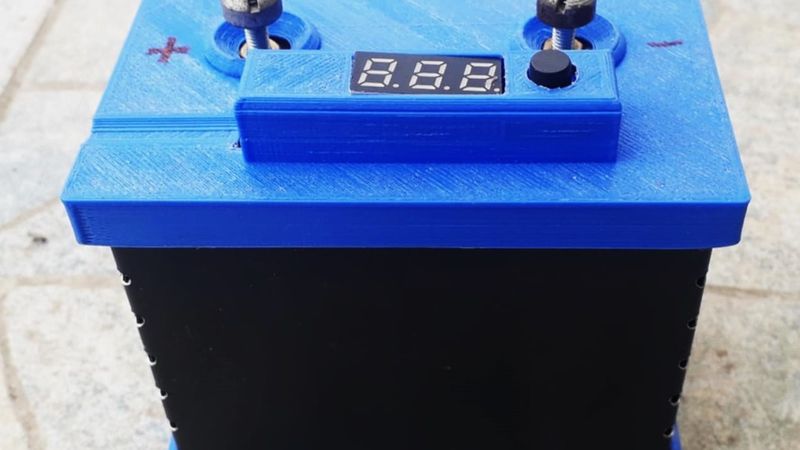
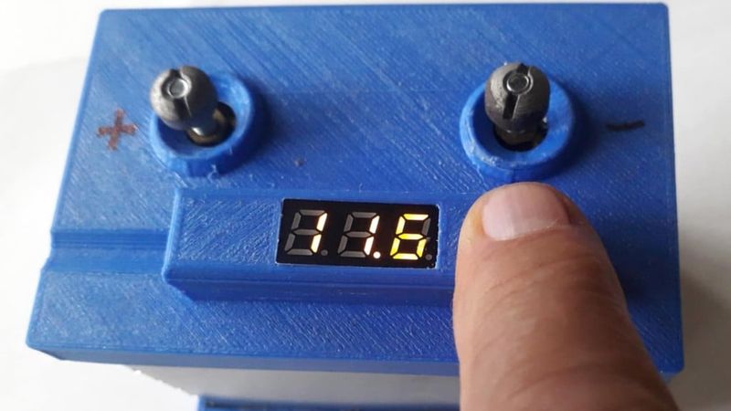
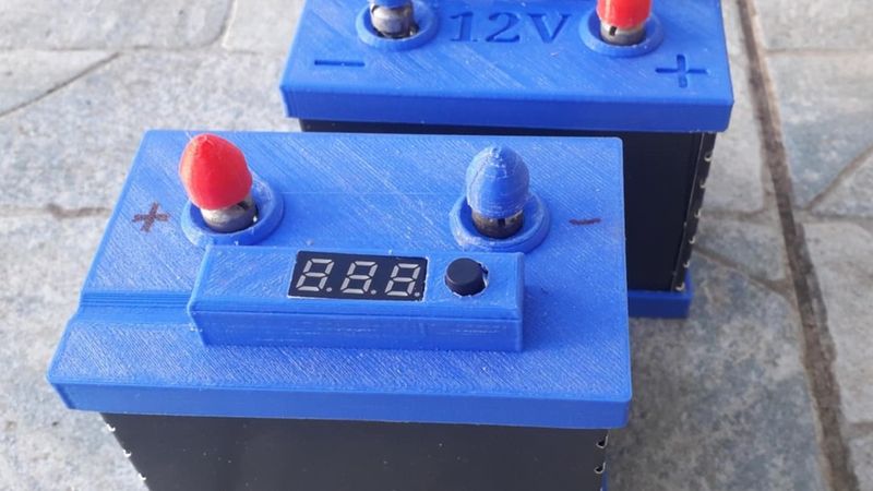
It incorporates a 20A Battery Management System (BMS) for charging. However, the discharge path bypasses the BMS. This is because some loads, like the diesel heater or motors installed, present a high inrush current during startup. This could trigger the BMS's over-current protection, cutting off the output. Important: The user must therefore carefully monitor the battery to prevent overload or over-discharge. The built-in voltmeter aids in this monitoring.
Construction Steps:
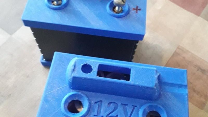
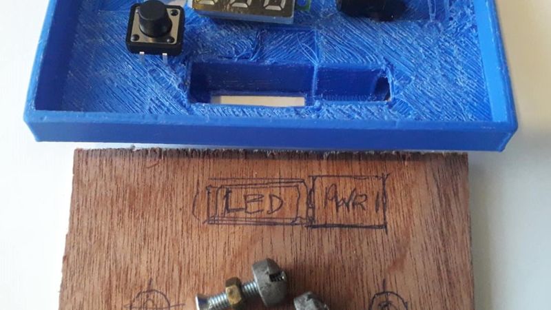
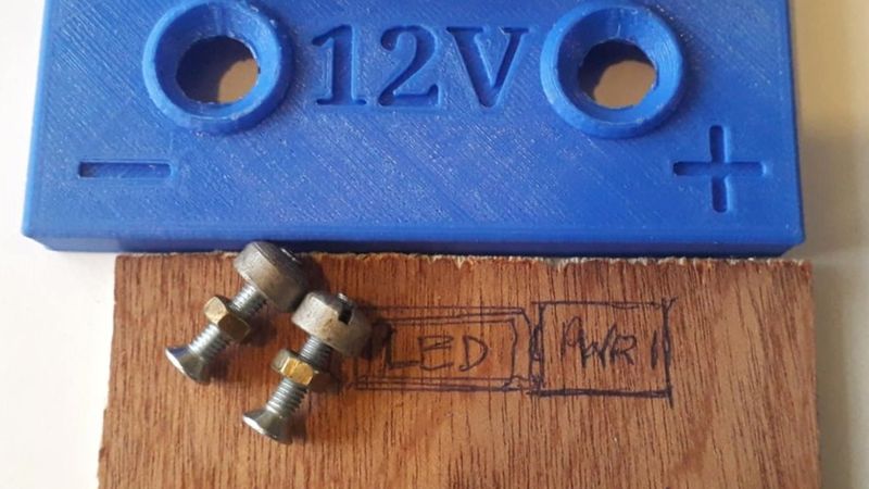
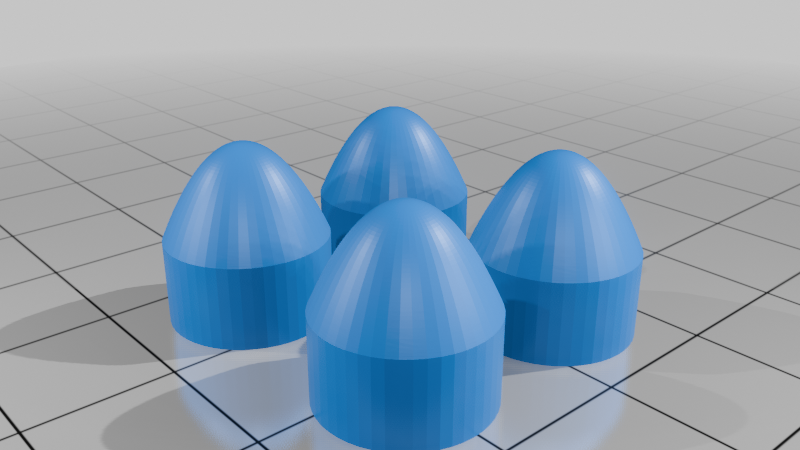
Print the 3D parts.
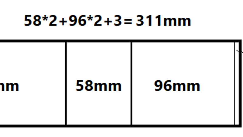
Prepare the aluminium plate: Cut a thin aluminium plate to the dimensions in the drawing. To create clean bends by hand, you can drill a series of 2.5mm holes spaced 1cm apart along the intended bend lines. If possible, form a folded "nest" along the 3mm edge as shown in the drawing.
Assemble the case: Glue the bent aluminium plate into the bottom 3D part and allow the adhesive to cure.
Build the battery pack: While the glue sets, assemble the 3S5P cell pack. Crucial: Ensure all cell voltages are equal before connecting them in parallel.
Make electrical connections: If you lack spot-welding equipment for nickel strips, you can use 4mm wide brass plate strips, soldered to create the connections between cells.
Final wiring:
Connect the main positive and negative battery terminals directly to the cell assembly.
Run the necessary thin balance wires from the cell groups to the BMS.
Connect the BMS input to the 5.5mm power socket (charger port).
Wire the digital voltmeter (DVM) module through the 12x12mm pushbutton switch to the battery terminals.
Safety Addendum
This battery is completely safe when charged and discharged exclusively through the 5.5mm power socket, as the BMS provides protection during charging/discharging.
The cell design and fabrication in general, offers inherent protection against short circuits , but responsible use is essential. The short-circuit current of the assembly is surely 250 to 500Amp. A direct short circuit across the main output (screw) terminals will almost certainly damage some or all of the cells.
Therefore, a 50 to 100A automotive blade or ANL fuse must be installed inside the battery housing (make space for it, increase the aluminium plate 75mm side to 80mm) , inline with the main positive discharge lead. This provides a final layer of protection and is strongly recommended before any use.
It could be used in motorbikes too but you must separate the charger and the start motor circuits.