Parametric 18650 Lipo ebike battery pack with case and OpenSCAD
Description
This started out as a small battery pack and case for my ebike project. It grew in to a flexible OpenSCAD script that I think others will find useful in a wide range of applications, not just ebikes.
I've shown example pictures of some of the many pack shapes it can make, and pictures of my own ebike battery project, for which I've also provided the .stl files that I printed.
Features and limitations
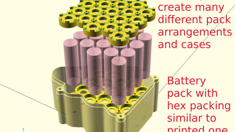
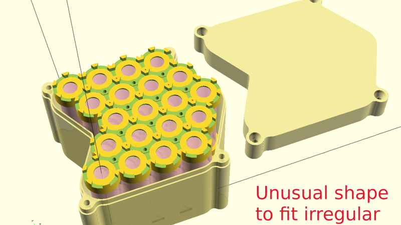
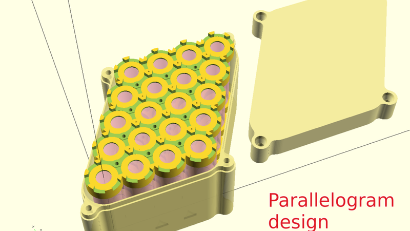
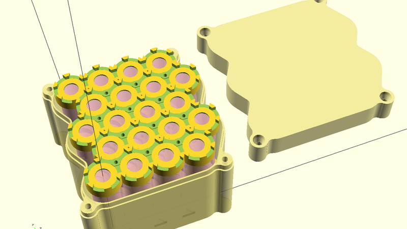
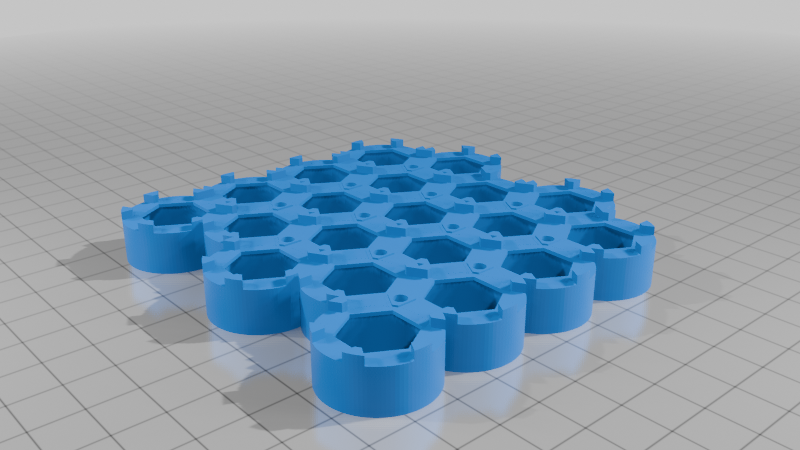
- It was originally designed for 'hex' packing ie offset staggered rows. You can specify the row and offset configurations to make almost any cell pack shape including irregular non-uniform shapes, which may be useful if you need to fit the pack in a tight space or fill out an irregular shaped space.
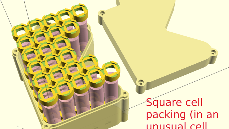
- I've now updated the code to give the option of square cell packing - this feature is less tested and I haven't printed any square pack designs.
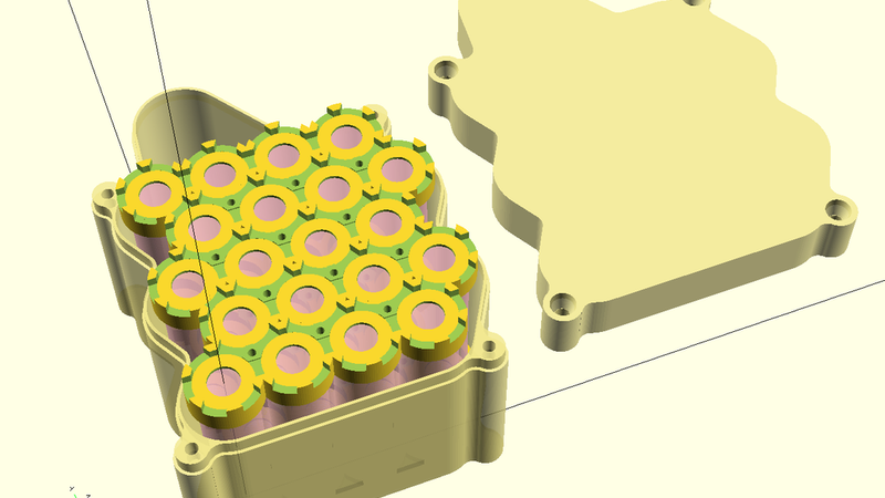
- The script makes both the battery packs and compatible case/lid - print either or both
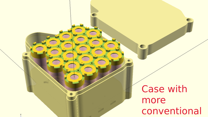
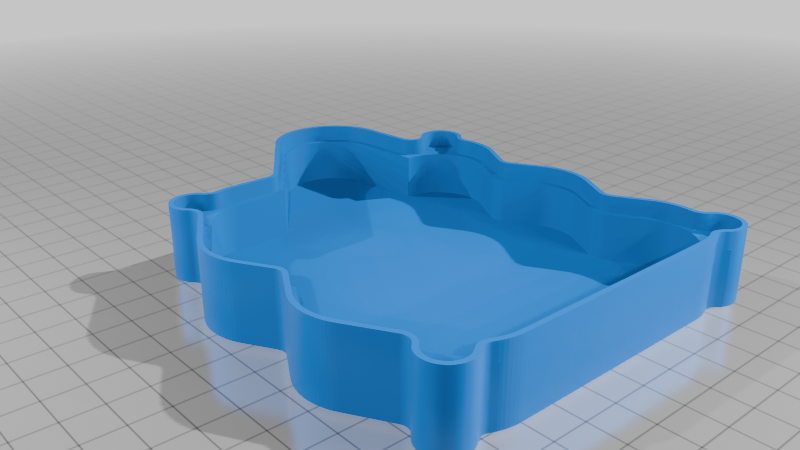
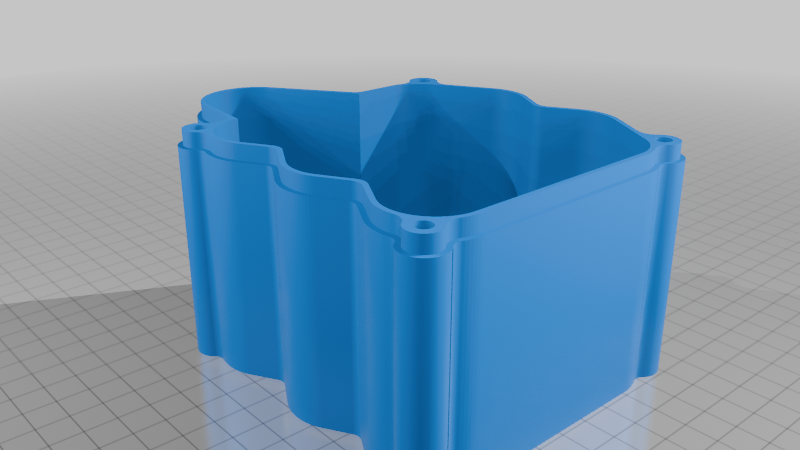
- The case shape can be configured to match the curved contours of the cell pack, or have more conventional straight sides. Many other things can be configured - see the notes in the .scad.
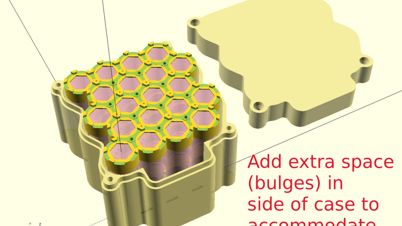
- You can add additional space ('bulges') to the case to accommodate any extras you need to fit inside such as switches, connectors, meters, circuit boards etc.
- It's not just for 18650s. The cell size is configurable, so you could build with any cylindrical cell, flux capacitor or whatever.
Design and printing notes
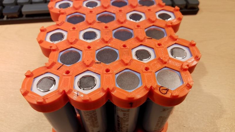
- I eventually settled on a cap design with a hexagonal hole. If you're using metal strips and spot welding, it gives you a straight edge to more easily bend the strip down to contact the end of the cell. The height of the cap top keeps the strip clear of the cell edge which is obviously the main concern. The script has a parameter to change to a round hole if you prefer.
- Printing - I printed the battery caps in the orientation of the .stl. I used normal supports in Cura - they add very little to the print time. Everything else is easy to print.
- Don't forget to mirror one set of caps if your pack shape isn't symmetrical.
- I printed in PETG. I think it's a fairly good choice considering potential fire and heat issues, but do your own research and exercise caution.
Details of my ebike battery and case make
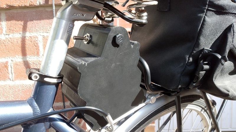
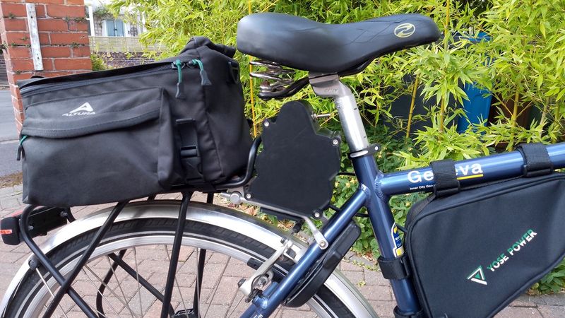
- I wanted a compact 18650 pack for my ebike project. I decided to fit the battery behind the seat post in the small unused space in front of the rack. It's not a very powerful build (see below for details) but it's intended for short journeys and low levels of pedal assist. I planned to build a supplementary pack that I'd only use on longer journeys so I can travel light most of the time. This pack weighs about 1.4 kilograms. As it's an ebike conversion, I'm trying to minimise weight.
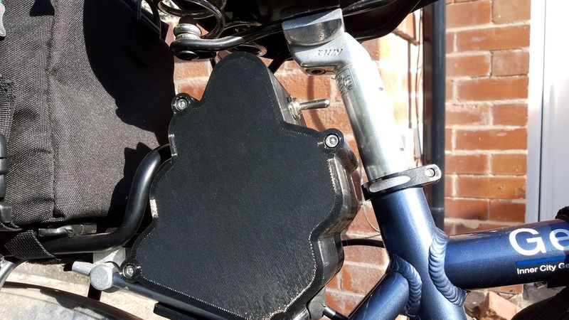
- I designed the case with curved sides to minimise space (even though it uses more filament) because I knew it would be a tight fit (tighter than it looks). I still had to rotate the seat post clamp to make it fit.
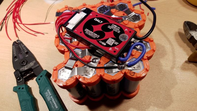
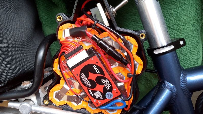
- The case includes additional space (the bulge on top) for the extra hardware. I added a power switch and a charging socket. I drilled the holes for the external hardware, but you could print the cutouts if you prefer (see notes in the .scad)
- The mounting hardware to attach to the rack isn't part of this project - each user's requirements will probably be different. I designed a bolted mount to attach to the rack and used CA glue to attach it to the base of the case. You'll need to design something to meet your own requirements.
- The case is mounted under the back of the saddle, so it does affect the saddle height range. Luckily I'm tall enough for this to be acceptable.
- To fix the lid, I used threaded inserts in the main case, and cap head allen bolts. You could use tapped holes or self-tappers if you prefer. Adjust the holes according to your requirements. I'd recommend using threaded inserts. They're easy to use. You don't need any fancy heat press tools. Here's my method for inserting them: Drill the holes out to match the outer diameter of the insert (to ensure good sizing and a clean, straight inner wall). Screw the insert on to the end of a long bolt and hold with pliers over a gas flame for about 25 seconds. You could also use a heat gun, or maybe a soldering iron. Insert the hot insert in to the 3d printed part and adjust so that it's nicely perpendicular. Allow to cool and unscrew the bolt. I designed and printed a small practice piece (a slab with some holes - see the .scad) to perfect my technique before doing it for real on the main case. I'll be using threaded inserts a lot more now that I've discovered how easy they are to fit. Buy them online - you can buy a mixed kit of about 250 different inserts for a modest price.
- The case lid bolts are M4 x 16. The brass inserts are M4 x 6 x 6. You need to drill the printed holes out to 6mm using a hand drill before fitting the inserts. I used a drill bit in a hand chuck.
- The power cable exits the case through a drilled hole on the lower front side (as mounted on the bike) - see pictures. I sealed round the cable with epoxy putty - there may be better options.
- I've included the .stl files that I used but I imagine many people will want a different configuration, so use the .scad to design what you want. See the pictures for examples of different configurations.
Some more details about my ebike conversion (not relevant to the 3d printed stuff but people will probably ask about these details)
- I used a Yose Power 250w, hub motor front wheel conversion kit - UK price (excluding battery) was £168. I was surprised at the cost, weight and size of the battery packs so I decided to build my own, which makes for a more satisfying project!
- 250w is the legal limit in the UK. It must be pedal assist (not throttle operated) and the motor assistance must cut out at 15.5 mph (that's not a speed limit - you can go faster but it must be pedal powered only at higher speeds). So, if you want to ride on-road and stay legal then that's your only option. I believe similar rules apply in the EU.
- Some people seem to hold the opinion that you shouldn't get a motor less than 500w or 750w, and that the only good option is mid-drive rather than hub drive. For enthusiast and off-road cyclists that may be true. And a mid-drive system may be more efficient in some ways. But based on my experience, I'm very pleasantly surprised at how good a 250w hub motor can be. The controller has 5 levels of pedal assist (as well as 'off'). I rarely go above level 1 or 2. It's great on hills, and on the flat I can ride one or two gears higher than I would otherwise (with corresponding increase in speed). I live in a coastal area where the strong winds lead me to ride less than I otherwise would. The motor conversion has solved that problem for me. I'd definitely buy the same kit again.
- If you want another opinion, watch the youtube video by Charlie DIYte who built a rear wheel version of the same kit. He rides it up a very steep hill near the end of the video - https://www.youtube.com/@CharlieDIYte - I have no connection to the channel.
- I wasn't sure if there would be any disadvantages to a front wheel hub motor (rather than rear wheel). My bike has hub gears (Shimano Nexus 7), so a rear wheel conversion wasn't an option. Based on my experience I'd say there's no disadvantage to a front wheel system, at least for relatively low power ebikes.
- The cells cost about £58 from Fogstar. Other costs included the BMS, charger and nickel strips etc which came from various ebay sellers. I raided the junk box for wire, fuse holder, switch and other hardware.
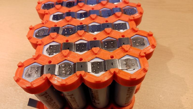
- You'll also need a cheap spot welder if you intend to spot weld rather than solder the cells. Soldering is possible but not recommended as the heat is more likely to damage the cells. Soldering is viable (and people certainly do it) but you need to have good soldering skills. If you accidentally damage a cell you may not realise immediately, and you'll probably have to disassemble the entire pack to resolve the problem. I used one of those Kekk welders sold online as a circuit board module (the purple one). See the youtube videos for the capacitor mod which improves the performance and prolongs the life of the power transistors. The newer model I bought came with the 'mods' buiIt in. You can see the welded strips in the pictures.
- The cells are 3.5 Ah in a 2P configuration (ie each cell position is really 2 cells in parallel), so that's a 7Ah 36V battery pack. Or about 250 watt-hours. That's small by most ebike standards. On a 12 mile (19 km) ride I drop about 2 volts from a full charge (ie from about 41V down to 39V). Volts basically equals Speed, so if you rode the battery down to its lower limit (say 30 volts) then you'd certainly lose top speed. The capacity may be insufficient for some riders. All I can say is: it's fine for me and I prefer the smaller size and weight. I guess I'd get at least 50 miles (80 km) from a full charge, though I've not tested it. Your mileage will obviously differ depending on riding style and terrain. If I was building this again I'd use exactly the same cell configuration. If you need more juice then build something bigger. The .scad will make you almost anything you can imagine!
- Possible improvements: I may think about adding a small buck converter in the case to give 5V output for USB powered devices, or for running power to the back light.
Warnings and Safety
- All risks are yours!
- There are many videos and websites with lots of good information about building battery packs. I recommend including a fuse in any battery pack build, even if you're using a BMS. That won't protect you from a short circuit within the pack itself, so try to minimise that possibility. I don't claim that my design or construction is necessarily best practice, so do your own research. These batteries are amazing, but they come with risks which shouldn't be underestimated.
- I'd advise building the pack outside or in an outbuilding, if you can. Also, when you charge the pack the first few times, do it outside your home if you can. Don't charge batteries unattended.
OpenSCAD script
- It's well documented - most people should be able to adjust the parameters and call the various modules to get what they want.
- It does require a bit of facility with OpenSCAD language if you want to add extra shapes to the case outline. I've shown a couple of examples in the code.
- It uses the BOSL2 library - see notes at the top of the .scad.
- If you think you've found a bug leave me a message and I'll see what I can do.
Conclusion
- As always, the project took vastly longer than my estimated timescale but I ended up with a very functional, unique battery pack and case. I don't think I could have bought anything similar, and I'm very happy with it. The relatively small battery capacity is actually perfect for my needs. I doubt I'll need to build the supplementary pack I was planning.
I hope you found some useful inspiration for your own project.
If you need a specific configuration and you're struggling with OpenSCAD then send me a message. I understand that not everyone can be a programmer. If it's a design that others might find useful then I'll see if I can upload .stl files for your design.
Donation link here if you want to support my work: https://paypal.me/ian3q