人体存在传感器PCB外壳模型Human Presence Sensor PCB Enclosure Model


Description
人体存在传感器PCB外壳模型 / Human Presence Sensor PCB Enclosure Model
项目简介
为了给家庭灯光自动化提供人体存在传感器数据,我设计并开源了一个基于ESPHome的"人体存在传感器+小夜灯"电路板。为了让传感器模块安装部署时可随意调节指向,以覆盖主要人员运动区域,我为电路板设计了此外壳模型。
配套PCB开源项目:人体存在检测+小夜灯
模型特性
- 安装方式可选:提供"可调节外壳"和"不可调节外壳"两个主要版本
- 供电接口可选:支持三种供电方式
- 数据线直插ESP32C3模块Type-C母座供电
- 底部USB-A公头供电
- 侧边Type-C母座供电
- 功能模块可选:根据PCB焊接情况提供三种版本
- 全功能版本
- 无LTR303光照孔版本
- 无SR602和麦克风孔版本
打印说明
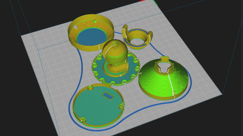
- 设计类型:所有构件专为FDM打印机设计
- 支撑要求:全部模型可无支撑打印
- 测试环境:已使用Voron2.4打印机、0.6mm喷嘴、ABS耗材测试通过
- 兼容性提示:暂未测试其他型号喷嘴和耗材的打印效果
主要版本详细介绍
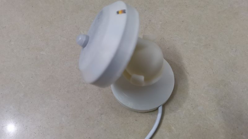
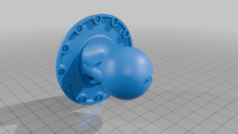
1. 可调节外壳版本
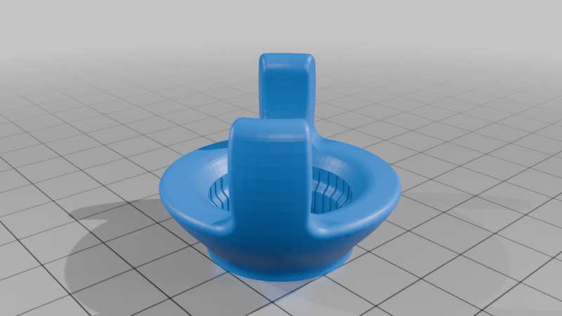
基于我改进的"Ball and Socket Mount Changed"球窝调节支架设计,可在三维空间上提供半球面任意角度的指向性调节!
改进版球窝支架项目:
- Thingiverse:Ball and Socket Mount Changed
- MakerWorld:球窝安装更改 Ball and Socket Mount Changed
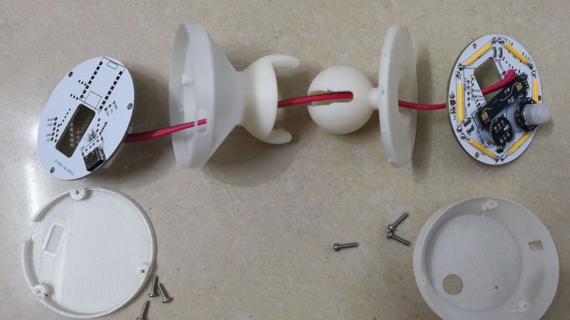
组装需求:需要打印5个零件完成组装
紧固方式:
- 球头部分:3个M2x10螺丝
- 窝底座部分:3个M2x8螺丝
- 替代方案:也可使用胶水粘接紧固
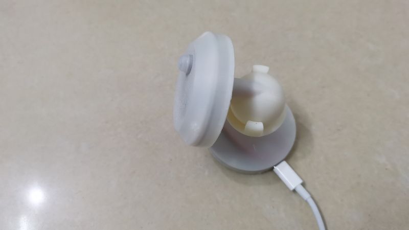
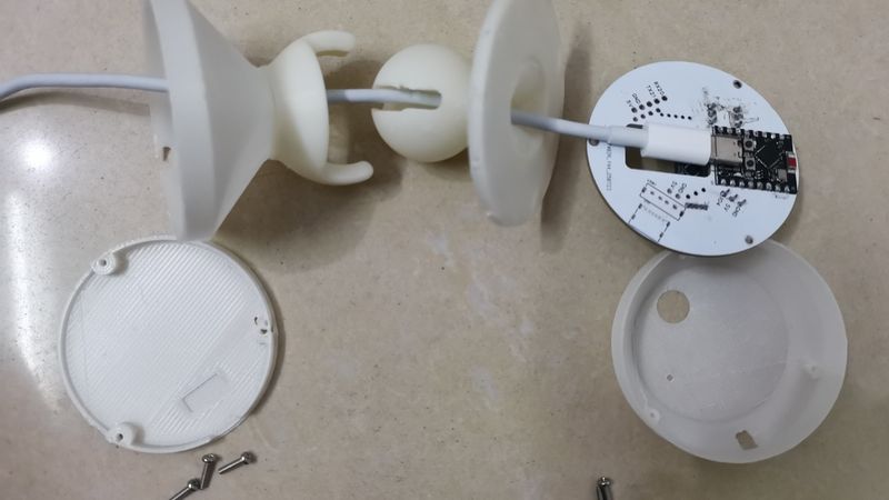
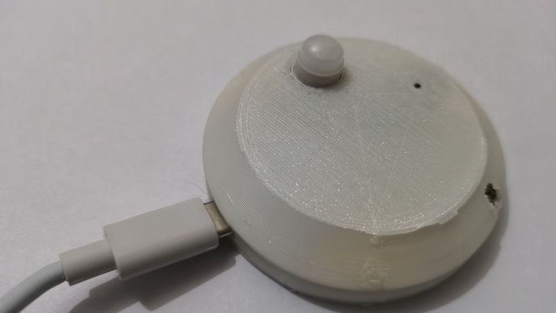
1.1 数据线直插ESP32C3模块Type-C母座供电(推荐)
特点:供电方法最简便,使用Type-C数据线穿过球窝支架穿线孔直插模块
安装方式:墙面部署时在外壳底座底部粘贴纳米胶
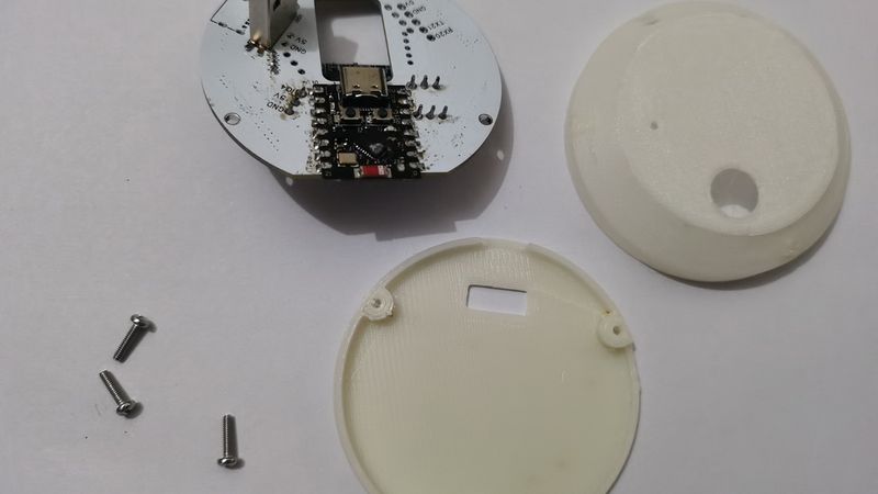
组装示意图:
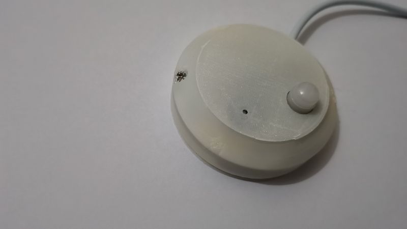
!最终效果
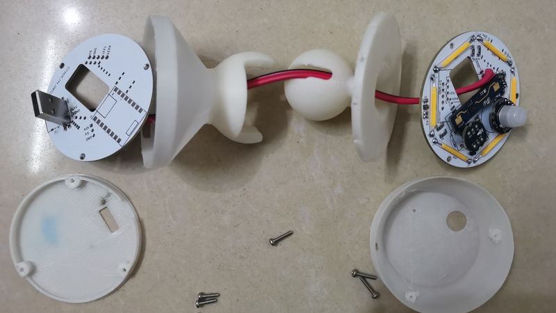
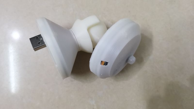
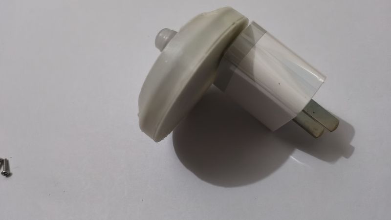
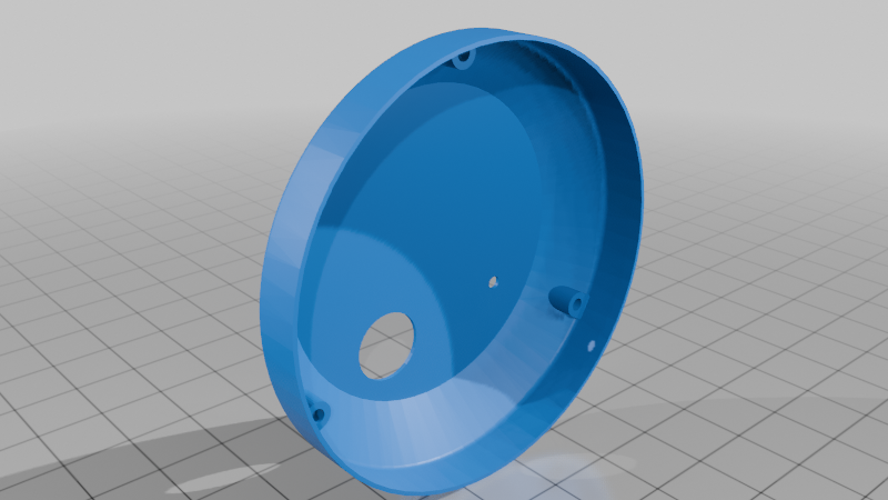
1.2 底部USB-A公头供电
特点:可直插USB-A充电头,供电同时固定底座
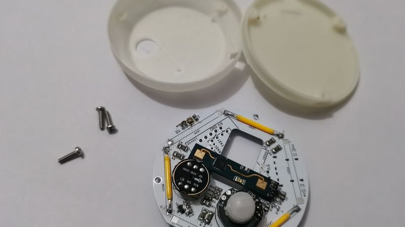
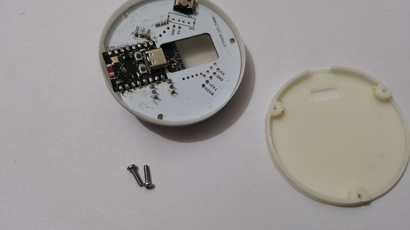
组装要求:需要使用2个PCB板
- 顶部PCB:焊接所有功能模块
- 底部PCB:仅焊接USB-A接头,通过导线连接5V和GND
组装示意图:
!最终效果
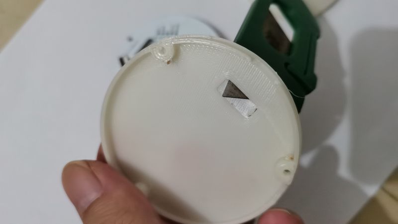
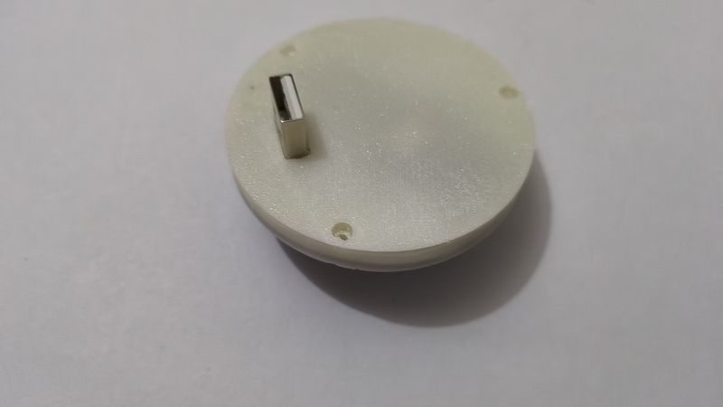
特殊说明:窝底盖为多方案兼容款,需用小刀裁出USB-A孔
!开孔示意
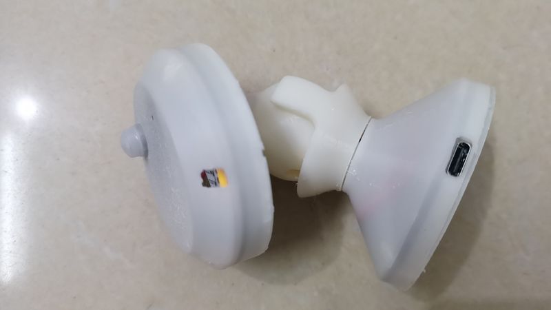
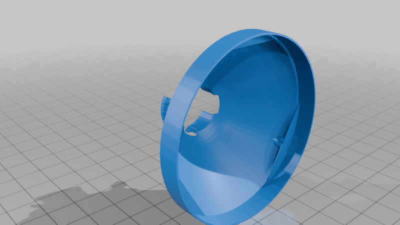
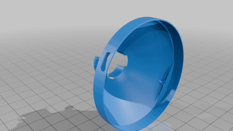
1.3 侧边Type-C母座供电
特点:简洁无拖尾,不占用数据线
组装要求:需要使用2个PCB板
- 顶部PCB:焊接所有功能模块
- 底部PCB:仅焊接Type-C母座,通过导线连接5V和GND
组装示意图:
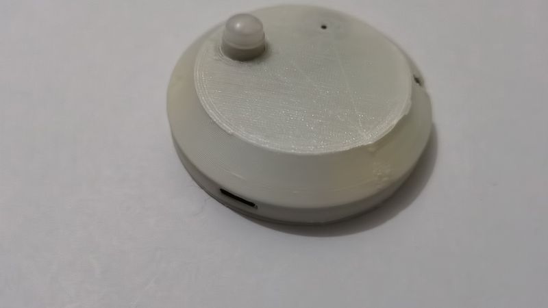
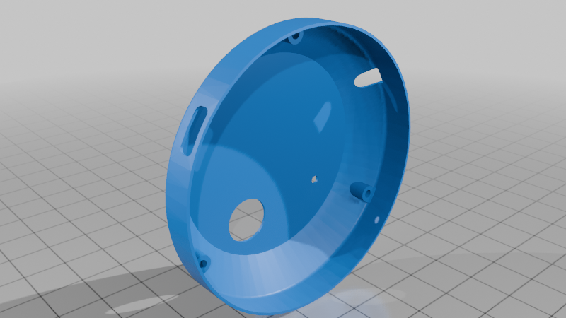
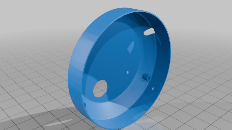
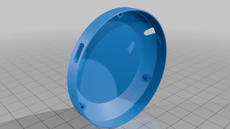
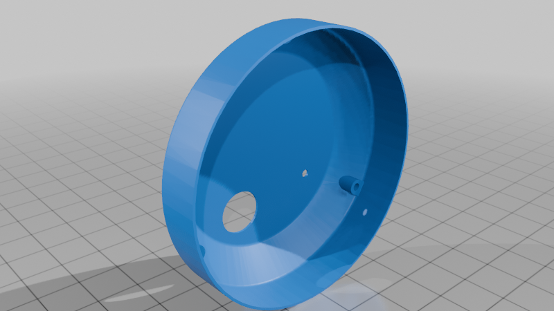
2. 不可调节外壳版本
特点:对比可调节外壳,体积更小,安装更简单
2.1 数据线直插ESP32C3模块Type-C母座供电(推荐)
!最终效果
紧固方式:3个M2x10螺丝或胶水粘接
2.2 底部USB-A公头供电
特殊说明:底盖为多方案兼容款,需用小刀裁出USB-A孔
紧固方式:3个M2x8螺丝或胶水粘接
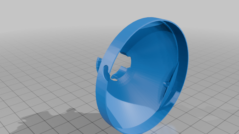
2.3 侧边Type-C母座供电
!最终效果
紧固方式:3个M2x8螺丝或胶水粘接
更新日志
- [2025-08-25] - 初始版本发布
致谢
感谢Thingiverse上的原始Ball and Socket Mount设计者,为本项目的可调节结构提供了灵感基础。
Project Introduction
To provide human presence sensor data for home lighting automation, I have designed and open-sourced an ESPHome-based "Human Presence Sensor + Night Light" circuit board. To allow flexible directional adjustment of the sensor module during installation and deployment for covering main movement areas, I designed this enclosure model for the circuit board.
Matching PCB Open-Source Project: Human Presence Detection + Night Light
Model Features
- Optional Installation Methods: Provides two main versions: "Adjustable Enclosure" and "Non-Adjustable Enclosure"
- Optional Power Interfaces: Supports three power supply methods
- Direct plug via data cable into the ESP32C3 module's Type-C female port
- Power supply via bottom USB-A male plug
- Power supply via side Type-C female port
- Optional Functional Modules: Three versions based on PCB soldering
- Full-feature version
- Version without LTR303 light sensor hole
- Version without SR602 and microphone holes
Printing Instructions
- Design Type: All components designed specifically for FDM printers
- Support Requirements: All models can be printed without supports
- Test Environment: Successfully tested with Voron2.4 printer, 0.6mm nozzle, ABS filament
- Compatibility Note: Printing effects with other nozzle models and filaments have not been tested yet
Detailed Introduction to Main Versions
1. Adjustable Enclosure Version
Based on my improved "Ball and Socket Mount Changed" ball-and-socket adjustment bracket design, it provides omnidirectional adjustment capability across a hemispherical range in 3D space!
Improved Ball-and-Socket Bracket Project:
- Thingiverse: Ball and Socket Mount Changed
- MakerWorld: 球窝安装更改 Ball and Socket Mount Changed
Assembly Requirements: Requires printing 5 parts for assembly
Fastening Methods:
- Ball head part: 3 × M2x10 screws
- Socket base part: 3 × M2x8 screws
- Alternative: Can also use adhesive for bonding and fastening
1.1 Direct Cable Plug into ESP32C3 Module Type-C Female Port (Recommended)
Features: Simplest power supply method, using Type-C cable passing through the ball-and-socket bracket wire hole to plug directly into the module
Installation Method: Apply nano tape to the bottom of the enclosure base for wall deployment
Assembly Diagram:
1.2 Bottom USB-A Male Plug Power Supply
Features: Can plug directly into USB-A charger, providing power while securing the base
Assembly Requirements: Requires using 2 PCB boards
- Top PCB: All functional modules soldered
- Bottom PCB: Only USB-A connector soldered, connected via wires to 5V and GND
Assembly Diagram:
Special Note: Socket base cover is multi-solution compatible, requires cutting out USB-A hole with a knife
1.3 Side Type-C Female Port Power Supply
Features: Clean without trailing cables, doesn't occupy data cable
Assembly Requirements: Requires using 2 PCB boards
- Top PCB: All functional modules soldered
- Bottom PCB: Only Type-C female port soldered, connected via wires to 5V and GND
Assembly Diagram:
2. Non-Adjustable Enclosure Version
Features: Compared to adjustable enclosure, smaller size, simpler installation
2.1 Direct Cable Plug into ESP32C3 Module Type-C Female Port (Recommended)
Fastening Methods: 3 × M2x10 screws or adhesive bonding
2.2 Bottom USB-A Male Plug Power Supply
Special Note: Base cover is multi-solution compatible, requires cutting out USB-A hole with a knife
Fastening Methods: 3 × M2x8 screws or adhesive bonding
2.3 Side Type-C Female Port Power Supply
Fastening Methods: 3 × M2x8 screws or adhesive bonding
Update Log
- [2025-08-25] - Initial version released
Acknowledgments
Thanks to the original Ball and Socket Mount designer on Thingiverse, who provided the inspirational foundation for this project's adjustable structure.
(English version translated by DeepseekR1 AI Model)