advancedPower & Batteries2-May-2020
Wireless charging system for electronic peephole

Anton Shagaev
Tashkent, UZ
4 days
--
6
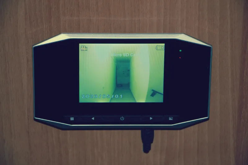
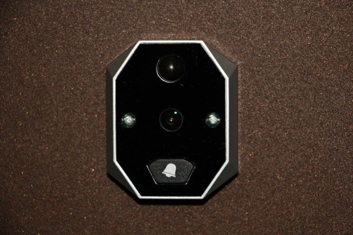
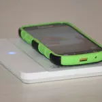
Friends, today I want to share my work on installing an electronic peephole with constant charging via induction plates. This peephole operates on a battery and needs to be periodically charged, like a phone, which is not very convenient, so the idea arose to make constant charging for this peephole wirelessly.
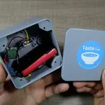
The peephole is equipped with a motion sensor and can record both video and take photos. Data recording is also done in the infrared range when there is no lighting in the hallway. Data is saved to a microSD card. Several ringtone melodies are also available to choose from. It does not have a built-in microphone, so there will be no sound in the video. After installing this peephole, my floor has become clean and very quiet :)
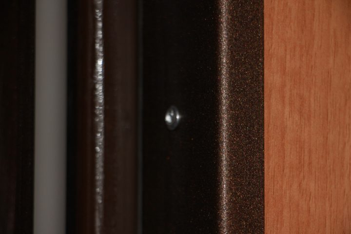
The main criterion for implementing this charging scheme is the presence of a gap between the edge of the door and the door frame—minimum 3mm.
Unfortunately, I do not have the actual installation process captured in photos, but I will try to talk about the main points of this installation.
What you'll need
Materials
- 1 pc
- 1 pc
- 1 pc
- 1 pc
- External DC power supply 12V/1A1 pc
- Cable with miniUSB connector, series B (male) 1 meter1 pc
- Wires1 pc
- Solder1 pc
- Heat shrink tubing for wires1 pc
- 1 pc
- Decorative windows for 3D printed induction plates2 pcs
- Painter's tape1 pc
- Rivets1 pc
- Hot glue1 pc
Tools
- Soldering iron1 pc
- Multimeter1 pc
- 1 pc
- Mini drill Dremel with cutting disc and abrasive attachments1 pc
- Center punch1 pc
- Electric drill with 3mm drill bit1 pc
- Heat gun for heat shrink1 pc
Steps
1
Pre-installation Wiring
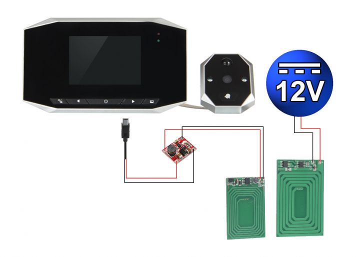
Electronic peephole connection diagram to wireless charger
Before starting the installation of the system, it is essential to make sure that everything works. The diagram is extremely simple, but schematically it looks like this:
Also, you need to be 100% sure that the gap between the door and the door frame is at least 3 millimeters. To check this, take a piece of plasticine, place it at the contact point of the door on the door frame, and close the door. You will get an imprint, the thickness of which can be measured with the depth gauge of a caliper.
Also, it is necessary to coat all surfaces of the plates with Urethane spray to prevent possible contact of the metal elements of the plates with the iron door. Let the plates dry thoroughly.
2
Marking of technological windows
Marking of technological windows
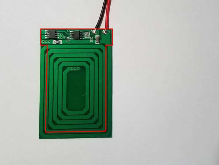
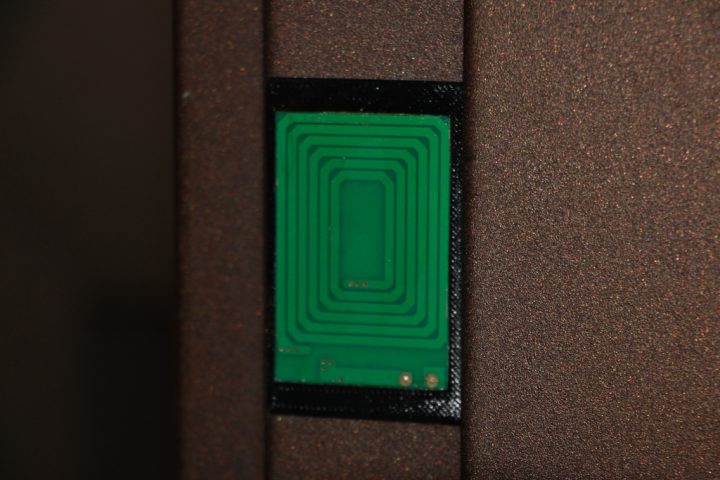
There are microcontrollers on the induction plates, so simply gluing the plates will not work; it is necessary to create technological windows in the door and the door frame. This will also reduce eddy currents, as the door and frame are metal.
Plate dimensions: for 12V (large) — 40.3mm(W) x 61.5mm(H), for 5V (small) — 31mm(W) x 47.7mm(H)
Determine the mounting location for the plates and protect this area with painter's tape, allowing extra margin for the width and height of the plates. The width and height of the technological window cutout can be determined by stepping back 5mm from each plate on three sides. On these 5mm of width, the plate will subsequently be glued using two-component adhesive. On the 4th side (the area with the microcontrollers), no step back is needed. The width of the cutout should be made to the full width of the plate. As a result, your window profile should resemble the letter T.
First, mark the technological window cutout on the door frame (for the large plate) and ensure that the levels of the lower and upper boundaries are visible on the door frame when the door is closed from outside your apartment (for this, add more painter's tape for better visibility of the marks). Using this, you will later transfer these levels to the door itself and will be able to symmetrically mark the technological window cutout in height for the second (small) plate. Symmetry in width is best achieved by measuring with a caliper, perpendicular to the inner plane of the door, to the outermost point of the induction plate on the door frame. Based on these measurements, you can find the width position for the small plate. These measurements are very important and must be very precise. It is better to check them several times, as it will be impossible to correct them if the marking is incorrect followed by cutting the technological windows.
3
Cutting of technological openings
First, take a center punch and mark the corners of the service window cutouts. After that, using an electric drill with a 3mm bit, make 8 holes on the edge of the door and 8 on the door frame. Next, carefully make the service window cutouts using a Dremel mini-drill with a cutting disc. This process is not quick and is noisy, so it's better to warn the neighbors in advance. :) After that, it's best to smooth out the burrs from the cutouts using abrasive attachments.
4
Installation of peephole and induction plates
Installation of peephole and induction plates
Installation of peephole and induction plates
Installation of peephole and induction plates
Installation of peephole and induction plates
We dismantle the old peephole and install the new electronic peephole according to the instructions. After that, we need to insert our cable with the miniUSB connector into the DC 5V port on the peephole monitor. We need to mark the position of the miniUSB connector plug using masking tape. To make the charging cable hidden in the door, we need to route it behind the decorative panel. We mark a point for the hole for the miniUSB cable.
To remove the decorative panel, you will need to remove the electronic peephole, drill out the rivets from the opposite end of the door, remove the metal mounting strip, remove the thumbturn, the lock handle with the keyhole plate, open the door wide, and pull out the decorative panel.
I recommend stripping all the insulation from the entire miniUSB cable to reduce the wire diameter, and leaving a section of about five centimeters with insulation near the connector itself so that it looks aesthetically pleasing on the decorative panel.
Next, we make a technological hole (5mm in diameter) in the metal door leaf inside your apartment, and also make one near the location of the induction plate. This is necessary so that the wires from the induction panel are routed under the decorative panel. We route the wires of the small induction plate through the 5mm technological hole.
We solder the wires of the door induction plate to the extension wires, and they, in turn, are soldered to the input contacts of the step-up mini-transformer. Don't forget to use heat shrink tubing on the wire solder joints. We drill a hole in the decorative panel for the miniUSB cable, thread the cable through the hole, and leave the necessary length outside according to the mark made earlier. On the reverse side, we secure the cable section near the hole with masking tape for reliable fastening.
Before soldering the wires of the miniUSB cable to the outputs on the step-up mini-transformer, we must make sure that we get 5 volts at the output. Without closing the door, this can be done with a multimeter. Apply 12 volts to the large plate, bring it close to the small one, and use a multimeter to measure the voltage at the output of the step-up mini-transformer. If we get 5 volts, then we solder the wires of the miniUSB cable to the outputs on the step-up mini-transformer.
I'll remind you again: put heat shrink tubing on all wire solder joints for insulation and connection reliability, and be sure to glue the solder joints on the step-up mini-transformer with hot glue.
We mount our step-up mini-transformer with hot glue into the technological hole of the thumbturn inside on the side.
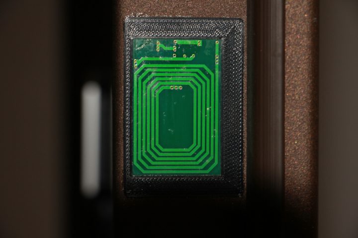
We mix the two-component glue Abro Epoxy Steel and carefully glue the plate onto the technological window. We secure the plate with masking tape for reliable fixation. Wait about 20 minutes. Remove the masking tape from the door.
Carefully put the decorative panel back in place. Problems may arise here when inserting the panel into the door due to friction. To reduce friction, I recommend vacuuming the grooves for the decorative panel and treating them with silicone spray.
We reinstall the decorative panel mounting strip and secure it with rivets using a rivet gun.
We perform similar operations for the large 12-volt induction panel.
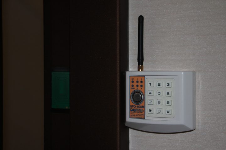
How to hide the wires and power them with 12 volts is up to you, but I routed them from the door frame (it's hollow) to the nearest free 12-volt port on the home alarm unit.
After closing the door, the battery in your electronic peephole will be constantly trickle-charged. When measuring the current on the mating induction plate, I got 250mA. Perhaps this won't be the best for the battery, but if it stops working after a year of constant trickle charging, I'll just buya new oneand it won't be a big problem.
If the battery is charging successfully, then finally we glue the decorative windows around the induction plates, which I printed on a 3D printer. Everyone will have their own, as door sizes vary. You can download my version of the decorative windows in the attached file.
That's all, I hope you can apply this installation scheme in your own home!
Discussion (0)
No comments yet. Be the first!
Maker
Anton Shagaev
Tashkent, UZ
Anton is the Founding Engineer at Tinkster. He translates industrial reliability into software architecture, ensuring the platform's core is built to last. Anton studied oil and gas engineering in the United States and also holds two honors degrees from Tomsk Polytechnic University.
Related Projects
AI Project Assistant
Tinkster Neural Core
Hi! I am the AI assistant for this project. Ask me any questions about the assembly, code, or components.