advancedSmart Home & IoT28-Dec-2021
Redmond SkyPort 103S socket control via Raspberry Pi

Anton Shagaev
Tashkent, UZ
1 day
--
7
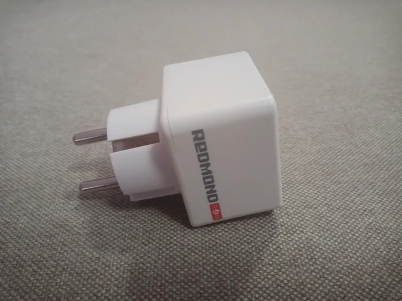
Friends, the automation of my home continues and today I would like to share with you about how to control the SkyPort 103S Bluetooth socket from Redmond via Raspberry Pi. The whole point is that in order to control this socket by voice through Alice at home, you need to have a constantly present smartphone or tablet with the application Ready for Sky and Bluetooth enabled. Then, in the Yandex application on your gadget, you link the account with your Ready For Sky account and the 103S socket starts being controlled by voice. I had no desire to allocate a separate smartphone or tablet with constantly enabled internet and Bluetooth for one socket, especially since I control all smart home devices through Raspberry Pi with a web server and "web hooks" of the "Domovenok Kuzya" service.
What you'll need
Steps
1
Installing Arduino IDE and necessary libraries
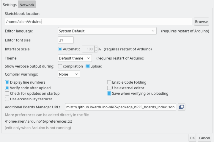
Installing Arduino IDE and necessary libraries
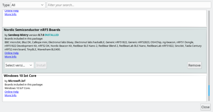
Installing Arduino IDE and necessary libraries
Installing Arduino IDE and necessary libraries
2
Connecting the programmer to the socket
Connecting the programmer to the socket
Connecting the programmer to the socket
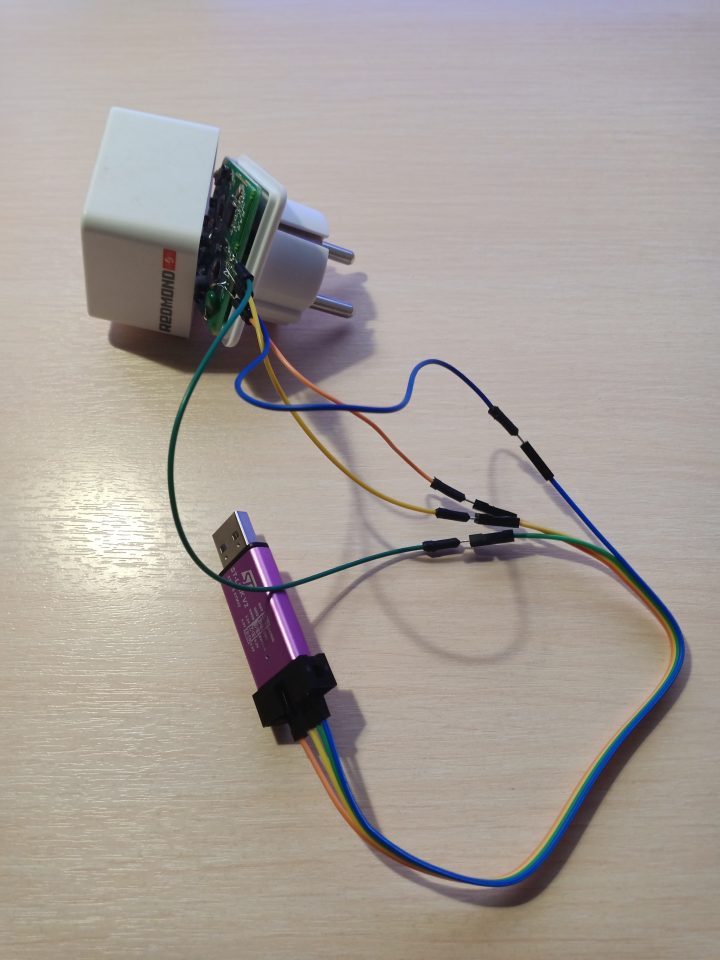
The programmer will come with a four-wire cable with "Female to Female" connectors for connection. I connected one end to the programmer according to the colors: Orange – 3.3V, Yellow – SWCLK, Green – GND, Blue – SWDIO.
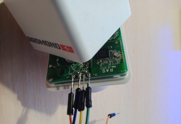
Disassemble the socket. It's quite simple to disassemble — unscrew the two screws with a countersunk hex head. On the socket's board there will be four similar inputs. From left to right:
3.3V — Orange wire
SWDIO — Blue
SWCLK — Yellow
GND — Green
On the opposite end of the cable, I used additional wires with "Male to Male" connectors, connected one end to the cable, and the other I simply temporarily soldered to the socket's board on the outputs corresponding to the colors.
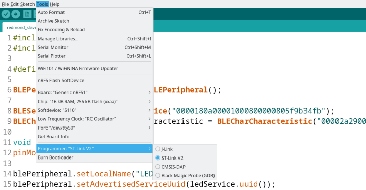
Now we need to flash the SoftDevice. This is done only once. Insert the programmer into the USB port and open the Arduino IDE.
Go to Tools and click on nRF5 Flash SoftDevice. A window will appear where you need to press the button Accept. That's it, the SoftDevice is flashed.
Now you can upload the sketch. Press Upload and the Arduino IDE will flash the nRF51822 chip. After that, you can remove the programmer from the USB port, desolder the four wires, and reassemble the socket. After assembling the Bluetooth socket, plug a desk lamp into it for testing. Connect the Bluetooth socket itself to a regular power outlet.
3
Turning on the socket via the terminal
Log into Raspberry Pi via SSH. Enter the command:
tinkster@almalinux:~#
1bluetoothctl
Next enter the command:
tinkster@almalinux:~#
1scan on
Find the MAC address of the device named LED and copy it to the clipboard.
Try to connect to the socket
tinkster@almalinux:~#
1connect XX:XX:XX:XX:XX:XX
where XX:XX:XX:XX:XX:XX is your socket's MAC address.
If the connection is successful, you will see the message
tinkster@almalinux:~#
1Device XX:XX:XX:XX:XX:XX Connected: yes2Connection successful
Next enter scan off and then exit to exit from bluetoothctl.
Find the Handler of our characteristic 00002a2900001000800000805f9b34fb.
Enter the command:
tinkster@almalinux:~#
1gatttool -t random --device= XX:XX:XX:XX:XX:XX --characteristics
And see something like
tinkster@almalinux:~#
1char value handle = 0x000b, uuid = 00002a29-0000-1000-8000-00805f9b34fb
0x000b – this is the Handler of this characteristic.
And now try to turn on our socket with the following command:
tinkster@almalinux:~#
1sudo gatttool -t random -i hci0 -b XX:XX:XX:XX:XX:XX --char-write-req -a 0x000b -n 01
Where hci0 – the name of the Raspberry Pi Bluetooth adapter
XX:XX:XX:XX:XX:XX – the socket's MAC address
0x000b – the characteristic Handler (you will have your own)
01 – the byte value to write to this characteristic
Accordingly, the command to turn off will be:
tinkster@almalinux:~#
1sudo gatttool -t random -i hci0 -b XX:XX:XX:XX:XX:XX --char-write-req -a 0x000b -n 00
Conclusion
Friends, that's all for now, this socket can now be controlled via Raspberry Pi, but the drawback of this method is that until Sandeep Mistry finds a way to connect via Bluetooth using passkey (i.e., a password), therefore, anyone within 10 meters of the socket will be able to turn it on using the appropriate equipment. I think you won't have any trouble 'attaching' terminal commands for controlling the socket via a web server and 'web hooks' to Alice. If you have suggestions on how to create a connection to the socket with a password, write in the comments.
Happy upcoming New Year to all of you! Wishing you all the best and only good luck in the new year!
Discussion (0)
No comments yet. Be the first!
Maker
Anton Shagaev
Tashkent, UZ
Anton is the Founding Engineer at Tinkster. He translates industrial reliability into software architecture, ensuring the platform's core is built to last. Anton studied oil and gas engineering in the United States and also holds two honors degrees from Tomsk Polytechnic University.
Related Projects

AI Project Assistant
Tinkster Neural Core
Hi! I am the AI assistant for this project. Ask me any questions about the assembly, code, or components.