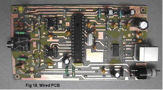
In order to be a 'Truly-DIY' Instructable a work around is presented to handle the FT232R device which comes in a 28 Pin SSOP package.
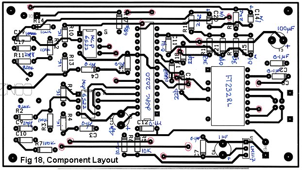
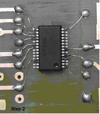
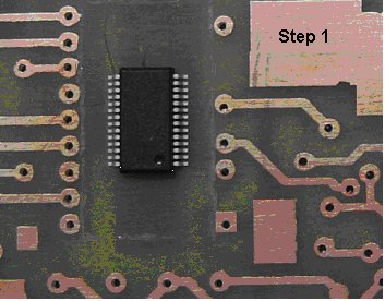
Step 1 & Step 2 show that the double sided PCB track widths are suited for the 'Toner-Transfer' method of PCB fabrication.
However, to handle the 28 Pin SSOP package a larger artificial footprint has been created and only the 12 pins which are required for the operation of the chip are extended carefully using thin copper wire to the pads of this artificial footprint. This is relatively easy to do while wearing spectacles with a +ive power or using a magnifying glass.
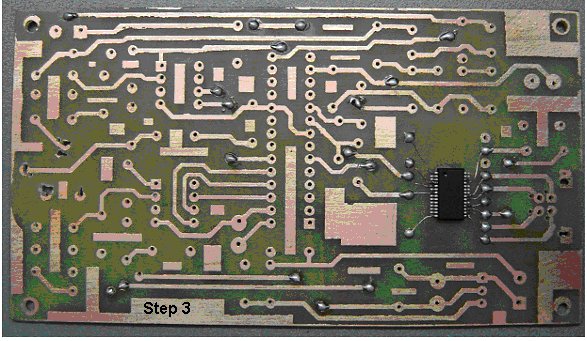
Step 3
As this is a DIY double sided PCB there are no plated through holes. It is necessary to connect the thru-hole-vias by soldering a through wire on both sides.
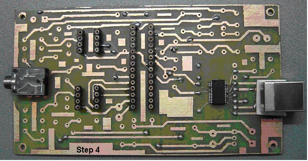
Step 4
In this step the IC bases and connectors are soldered on the PCB.
It is necessary to check that pads on the top layer are soldered on top and if necessary at the bottom also in order to handle the non availability of plated through holes for component pins.
Additionally some pads for the connectors on the top layer are inaccessible because they are covered by the connector body. In this case small holes need to be drilled near these pins and the pad connection extended to the bottom by soldering a thin copper wire through the board. This needs to be done carefully so as not to create any accidental connection to neighboring tracks.
A thin piece of paper or any insulating material needs to be placed under the USB connector so that the body does not short with tracks on the top of the board.
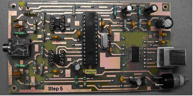
Step 5
Soldering the passive components and insert the ICs.
Note how the MCP6S22 which comes in a Small 8-pin MSOP Package is handled.
In this case cut pieces from the other component leads are inserted into the base and soldered carefully to the MCP6S22 pins. This helps in taking care of these devices which come both in the Small 8-pin MSOP Package or the 8-pin DIP package.
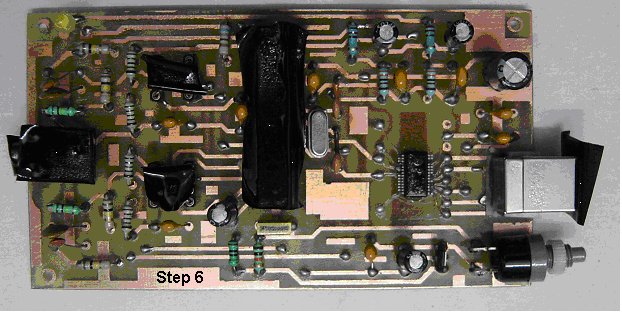
Step 6
Conformal Coating
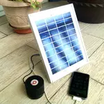
If the dsPIC30F2020 has been programmed with the .Hex fuse file and the pads checked once more for proper soldering on both sides wherever necessary, the circuit can be powered up and checked for operation.
Once the basic operation is checked along with the Host PC loaded with appropriate Windows/Linux software the board needs to be cleaned of excess solder flux using ISO-Propyl Alcohol or Spirit and dried.
After covering the IC base locations with insulating tape the board is sprayed on both sides with a conformal coating for protection.
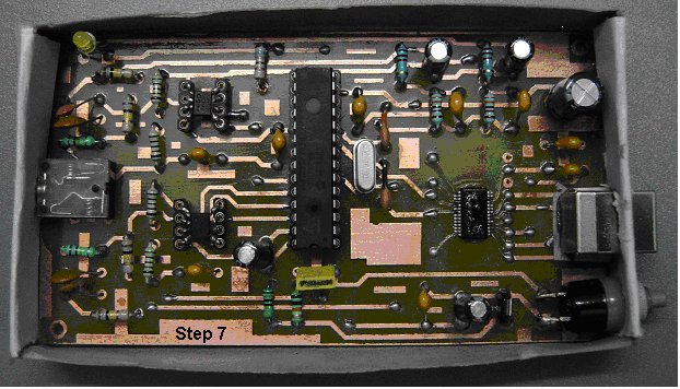
Step 7,8 & 9
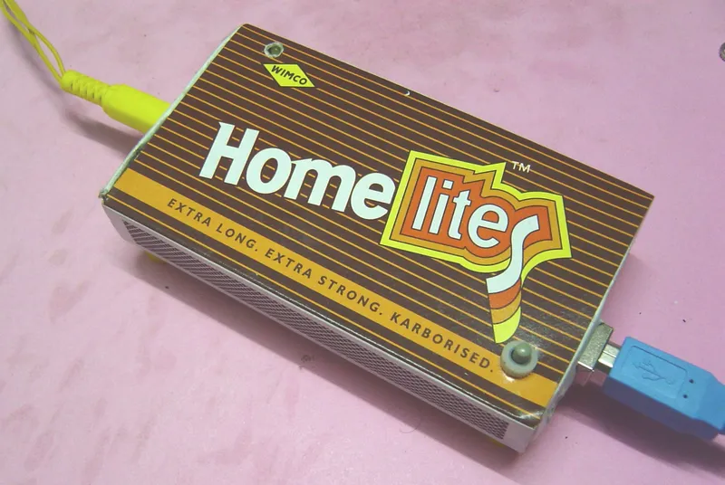
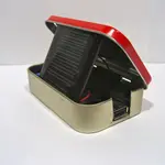
Assembling inside the Matchbox Inner Cardboard Container. Sliding into the outer cover and sticking the legs.
Holes need to be cut for the connectors and reset switch using a sharp knife and the board carefully fitted into the inner cardboard container of the matchbox.
Next, this can be slid into the outer cover with a hole for the LED and legs stuck onto the bottom
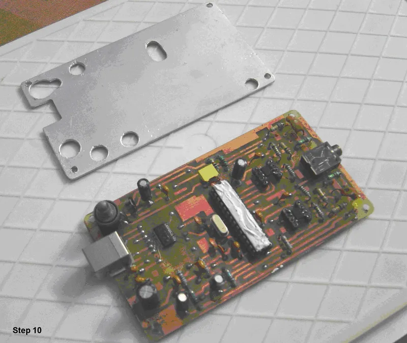
Step 10
Are we now ready ? No !
While practically operating the system it was noticed that the dsPIC30F2020 runs hot to the touch. This is particularly so because of operating at a clock frequency just outside specifications, the enclosure and when the USB 5V is slightly on the 5+ side.
This could lead to intermittent communication between the PIC and Host PC.
A heat-sink is added to eliminate this problem.
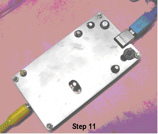
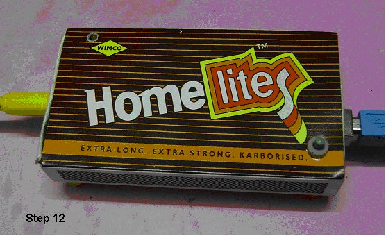
Step 11 & 12
The heat sink uses 0.8 mm aluminum fabricated with openings for the taller components.
The reset switch is turned to the vertical position.
Heat sink compound is added over the processor IC.
And the heat sink plate fixed using the screws through the mounting holes.
This compound unit is now fitted back into the inner cardboard and slid into the top cover.
We are done and the DIY-USB-Oscilloscope is ready to use.