expertLinux & Homelab27-Aug-2025
DIY NVMe Cooling for the HPE ProLiant Gen 10 Plus Microserver

Anton Shagaev
Tomsk, RU
3 days
245
186
Hello friends! Today we will talk about how to upgrade the HPE Proliant Gen 10 Plus microserver by installing a server NVMe drive from Samsung (model PM1725B, 1600 GB) . NVMe SSDs are very fast compared to SATA SSDs (10-12 times faster), and I recently learned that it is possible to install a Samsung HHHL (half-height, half-length) NVMe SSD into the PCIe slot of my server and subsequently install Linux on it (this will be the topic of the next guide).
However, the problem with NVMe SSDs is that they get very hot (this drive was already at 57 degrees Celsius in idle mode) . It was decided to build a custom cooling system with a PWM fan because the server motherboard has no free PWM headers.
What you'll need
Materials
- 1 pc
- 1 pc
- 1 pc
- 1 pc
- 1 pc
- 2 pcs
- 1 pc
- 1 set
- 3D-printed Air Duct1 pc
Steps
1
Installing the Server NVMe Drive
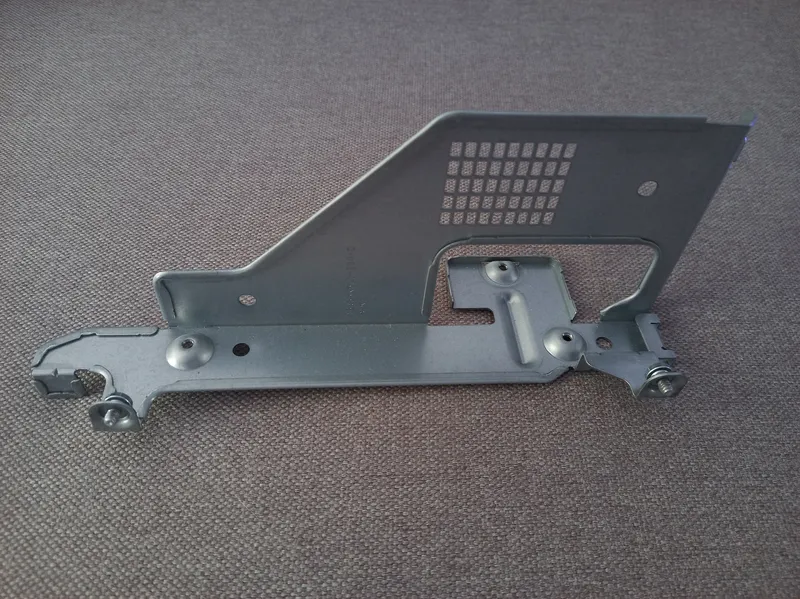
Metal bracket
Install the Samsung PM1725B server NVMe drive into the PCIe4 x16 slot, having first removed the iron bracket from the Riser board, as it will interfere with the installation of the PWM fan .
Turn on the server and check the UEFI to see if the drive is detected.
If everything is fine, boot into Linux and check the NVMe drive temperature with the command (path to NVMe /dev/nvme0n1, yours may differ):
tinkster@almalinux:~#
1watch -n 2 'nvme smart-log /dev/nvme0n1 | grep -i temperature'
In my case, it was already 57 degrees in idle mode, which is quite high. Turn off the server.
2
Flashing the Seeeduino Microcontroller
Seeeduino microcontroller
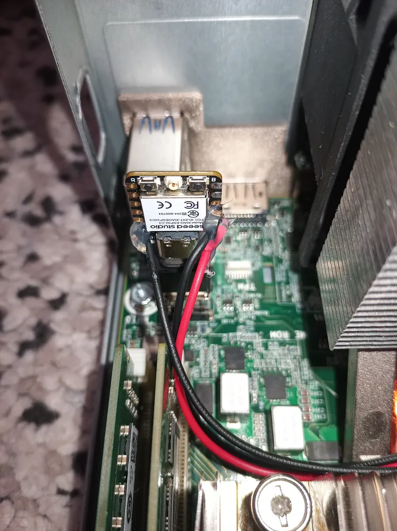
We will install the Seeeduino microcontroller with the adapter into the free USB 3.2 Gen 1 port inside the Proliant Gen 10 Plus microserver, originally intended for a boot flash drive .
Flash the controller with the following sketch in the Arduino IDE:
tinkster@almalinux:~#
1#define FAN_PWM 4 // PWM on GPIO42#define FAN_TACH 3 // Tachometer on GPIO334const int pwmFreq = 25000; // PWM Frequency (Hz)5const int pwmResolution = 8; // PWM Resolution (bits)6volatile unsigned long rpmPulses = 0; // Number of pulses from tachometer7unsigned long lastDataTime = 0; // Time of last temperature receipt8bool emergencyMode = false; // Emergency mode (no data)9const int pulsesPerRev = 2; // Tachometer pulses per revolution1011int currentPwm = 25; // Current PWM12int targetPwm = 25; // Target PWM1314// Curve defining relationship between temperature and fan PWM15struct FanCurvePoint {16int temp;17int pwm;18} fanCurve[] = {19{30, 25},20{45, 40},21{55, 120},22{65, 200},23{75, 255}24};2526const int curvePoints = sizeof(fanCurve) / sizeof(fanCurve[0]);2728// Interrupt handler for counting tachometer pulses29void IRAM_ATTR countRPM() {30rpmPulses++;31}32// End: tachometer pulse counting function3334void setup() {35Serial.begin(115200);36delay(500);3738// PWM setup: using ledcAttach() according to Espressif Arduino 3.x39ledcAttach(FAN_PWM, pwmFreq, pwmResolution);4041// Set initial PWM value42ledcWrite(FAN_PWM, currentPwm);4344// Tachometer input setup with pull-up resistor45pinMode(FAN_TACH, INPUT_PULLUP);46attachInterrupt(digitalPinToInterrupt(FAN_TACH), countRPM, FALLING);4748lastDataTime = millis();49Serial.println("=== FAN Controller started ===");50}51// End: initialization and setup5253void loop() {54// Read data from Serial to get temperature55if (Serial.available()) {56String input = Serial.readStringUntil('\n');57input.trim();58if (input.startsWith("temperature")) {59int temp = input.substring(input.indexOf(':') + 1).toInt();60if (temp > 0 && temp < 120) {61targetPwm = mapTemperatureToPwm(temp);62lastDataTime = millis();63emergencyMode = false;64} else {65Serial.printf("Invalid temp: %d\n", temp);66}67}68}6970// If no data received for over 8 seconds — enable emergency mode with max PWM71if (millis() - lastDataTime > 8000) {72emergencyMode = true;73targetPwm = 255;74Serial.println("EMERGENCY: No data from NVMe!");75}7677smoothFanSpeed();7879// Output RPM to Serial every 2 seconds80static unsigned long lastRpmTime = 0;81if (millis() - lastRpmTime > 2000) {82detachInterrupt(digitalPinToInterrupt(FAN_TACH));83unsigned long rpm = (rpmPulses * (60000 / 2000)) / pulsesPerRev;84Serial.printf("RPM: %lu (pulses: %lu)\n", rpm, rpmPulses);85rpmPulses = 0;86attachInterrupt(digitalPinToInterrupt(FAN_TACH), countRPM, FALLING);87lastRpmTime = millis();88}89}90// End: main processing loop9192// Function that returns PWM based on temperature according to the curve,93// turns off the fan at temperatures below 30,94// and prevents PWM from dropping below 24 when the fan is on.95int mapTemperatureToPwm(int temp) {96if (temp < 30) return 0; // Fan off when temp < 30°C97for (int i = 0; i < curvePoints - 1; i++) {98if (temp <= fanCurve[i + 1].temp) {99int pwm = map(temp, fanCurve[i].temp, fanCurve[i + 1].temp,100fanCurve[i].pwm, fanCurve[i + 1].pwm);101if (pwm < 24) pwm = 24; // Minimum PWM for stable fan startup102return pwm;103}104}105return fanCurve[curvePoints - 1].pwm;106}107// End: temperature to PWM mapping function108109// Function to smoothly change fan speed to target value110// Minimum PWM 24 if targetPwm is not 0, otherwise full stop (0)111void smoothFanSpeed() {112if (targetPwm < 24) {113// If target is below startup threshold — turn fan off immediately114currentPwm = 0;115} else {116// Smoothly approach targetPwm117if (currentPwm < targetPwm) {118currentPwm += 5;119if (currentPwm > targetPwm) currentPwm = targetPwm;120} else if (currentPwm > targetPwm) {121currentPwm -= 2;122if (currentPwm < targetPwm) currentPwm = targetPwm;123}124// Minimum threshold for startup and maintenance125if (currentPwm < 24) currentPwm = 24;126}127ledcWrite(FAN_PWM, currentPwm);128Serial.printf("PWM set to: %d\n", currentPwm);129}130// End: smooth fan speed change
This sketch controls the speed of a 4-wire fan with PWM control and tachometer feedback. It regulates fan rotation speed depending on the temperature received via the serial port from the NVMe drive, using a preset temperature curve. The sketch includes an emergency mode with maximum RPM if data is missing for more than 8 seconds, provides smooth speed changes, and periodically outputs current RPM readings to the port monitor .
Next, turn on the server.
In Linux, create the file nvme_temp_sender.sh:
tinkster@almalinux:~#
1# nano /usr/local/bin/nvme_temp_sender.sh
nvme_temp_sender.sh
1#!/bin/bash23DEVICE="/dev/serial/by-id/usb-Espressif_USB_JTAG_serial_debug_unit_XX:XX:XX:XX:XX:XX-if00"4NVME_DEVICE="/dev/nvme0n1"56while true; do7# Wait for ESP32 device to appear8while [ ! -e "$DEVICE" ]; do9echo "[WARN] ESP32 not found, waiting for connection..."10sleep 211done1213echo "[INFO] Connecting to $DEVICE"1415# Open device for writing via descriptor 316exec 3> "$DEVICE"1718while true; do19# If device is disconnected — exit inner loop to reconnect20if [ ! -e "$DEVICE" ]; then21echo "[WARN] ESP32 disconnected, restarting..."22exec 3>&-23break24fi2526# Read NVMe temperature27TEMP=$(nvme smart-log "$NVME_DEVICE" 2>/dev/null | awk '/^temperature/ {print $3; exit}')2829if [[ -z "$TEMP" ]]; then30echo "[ERROR] Failed to get NVMe temperature!"31TEMP=032fi3334# Send string to ESP3235echo "temperature: $TEMP" >&336sleep 237done38done
The path to the Seeeduino (DEVICE="/dev/serial/by-id/usb-Espressif_USB_JTAG_serial_debug_unit_XX:XX:XX:XX:XX:XX-if00") will be unique to you; find it in /dev/serial/by-id/. Also, the path to the NVMe (NVME_DEVICE="/dev/nvme0n1") might be different for you .
Save the file and make it executable:
tinkster@almalinux:~#
1# chmod +x /usr/local/bin/nvme_temp_sender.sh
Next, create the service nvme_temp_monitor.service:
nvme_temp_monitor.service
1# nano /etc/systemd/system/nvme_temp_monitor.service
And paste the following into the file:
nvme_temp_monitor.service
1[Unit]2Description=NVMe Temperature Monitor for ESP32 over USB Serial3After=network.target45[Service]6Type=simple7User=root8ExecStart=/usr/local/bin/nvme_temp_sender.sh9Restart=always10RestartSec=511StandardOutput=syslog12StandardError=syslog13SyslogIdentifier=nvme_temp_monitor1415[Install]16WantedBy=multi-user.target
Save the file and reload all systemd unit files without restarting systemd itself:
tinkster@almalinux:~#
1# systemctl daemon-reload
Enable autorun for the nvme_temp_monitor service in the current session:
tinkster@almalinux:~#
1# systemctl enable --now nvme_temp_monitor.service
Next, start the nvme_temp_monitor service:
tinkster@almalinux:~#
1# systemctl start nvme_temp_monitor
Briefly, the nvme_temp_monitor service runs a script (nvme_temp_sender.sh) that reads the NVMe drive temperature every 2 seconds and sends it via the USB serial port to the Seeeduino. If the Seeeduino is unplugged/plugged back in, the script reconnects automatically.
3
Connecting the Seeeduino Microcontroller to the PWM Fan
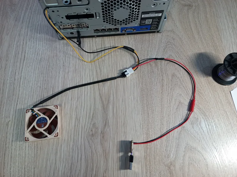
Connecting the Seeeduino microcontroller to the PWM fan and 12-volt power.
How it looks in the microserver
Insert the microcontroller into the USB 3.2 Gen 1 port. Take a 2-pin female connector and solder the black wire to D1 (GPIO 3) and the red wire to D2 (GPIO 4) on the microcontroller. Then we need to cut the connecting wires from the 4-Pin Molex that go to the white 4 PWM connector (yellow and black wires). From the black 4 PWM connector, physically pull out the black and red wires with their locking pins (you will have to ruin one black 4 PWM connector and cut the wires from the 4-Pin Molex to do this) and insert the locking pins into the free holes of the white 4 PWM connector (black on the left, as this is PWM).
Next, solder the black and red wires of the white 4 PWM connector to the corresponding colored wires of a 2-pin male connector and connect it to the 2-pin female on the microcontroller. Use heat shrink tubing on all wire solder joints.
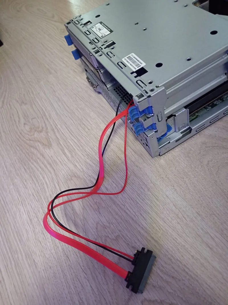
We will take 12-volt power for the PWM fan from the SATA 7+15pin connector on the server from Bay 4. Take the data cable (Cablexpert CC-SATAMF-715-50CM) and cut off the yellow (12 volts) and two black wires (Ground) from the female connector. Insulate the cut areas of the wires from the female connector and all contacts of the female connector using hot glue. Insert the male connector of the cable into the SATA 7+15pin female in Bay 4.
I had to sacrifice Bay 4 to get power from SATA, but in my disk configuration, it was always empty, so this did not affect anything. Solder the yellow and black wires from the connector to the wires of the corresponding color on the white 4 PWM connector. Solder the second black wire to Ground on the microcontroller, also via a 2-pin connector (snipping off the second red wire from it, as it is not needed). This is not mandatory, as Ground on SATA and Ground on the microcontroller (via USB-A) should be common. I tried to do everything via connectors so that it would be convenient to connect/disconnect everything later.
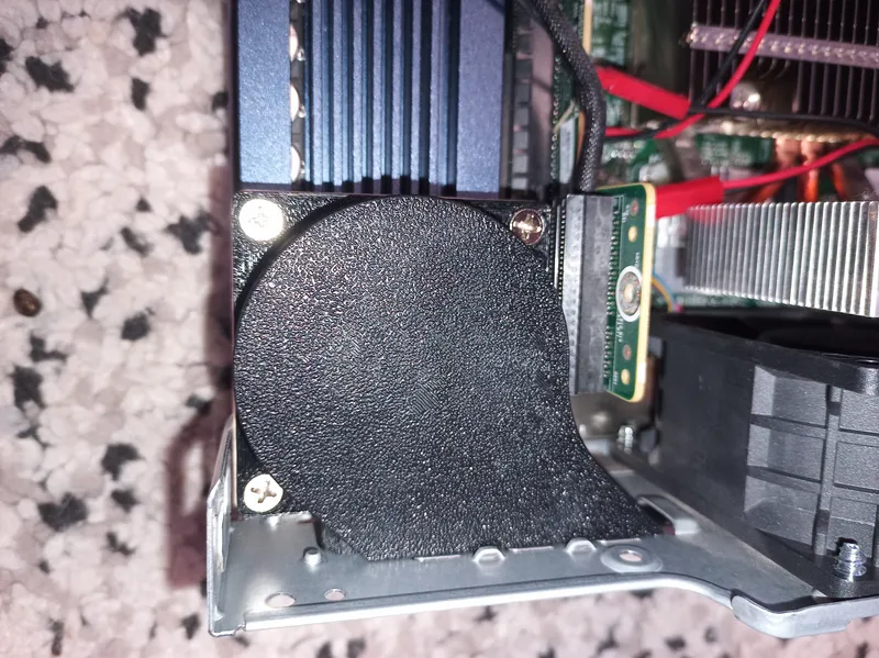
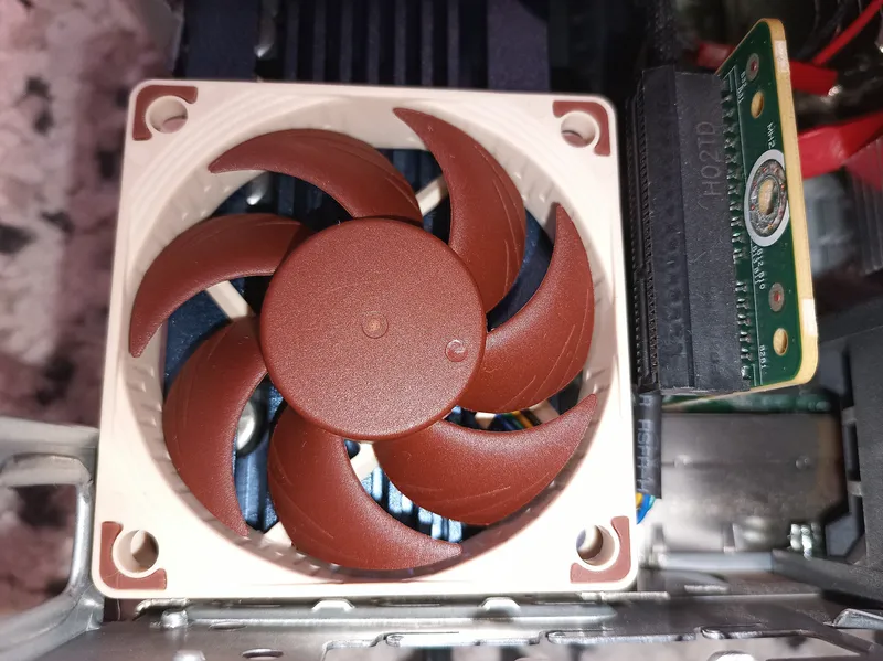
Place the PWM fan itself on the NVMe drive heatsink in "blow" mode (i.e., blowing onto the heatsink). Also, remove the blanking plate from the rear wall of the server intended for iLO. Air intake will be carried out from this cutout on the rear wall.
4
Testing the PWM Fan
Turn on the server and check the RPM and PWM signal with the command:
tinkster@almalinux:~#
1cat /dev/ttyACM0 | awk '/RPM:/ {rpm=$2} /PWM set to:/ {pwm=$4} rpm && pwm {print "RPM=" rpm, "PWM=" pwm}'
If everything is fine, you should see something like this:
tinkster@almalinux:~#
1RPM=1410 PWM=1542RPM=1410 PWM=1543RPM=1410 PWM=1594RPM=1800 PWM=1595RPM=1800 PWM=1596RPM=1800 PWM=159
You should see changes in RPM and PWM.
Also, check the temperature with the command:
tinkster@almalinux:~#
1watch -n 2 'nvme smart-log /dev/nvme0n1 | grep -i temperature'
You should see something similar to:
tinkster@almalinux:~#
1temperature : 44 C2Warning Temperature Time : 03Critical Composite Temperature Time : 04Temperature Sensor 1 : 44 C5Temperature Sensor 2 : 43 C6Temperature Sensor 3 : 43 C
In my case, the temperature dropped by 13 degrees in idle mode, which is an excellent result. But we will see later how the temperature behaves under load.
5
Air Duct Design
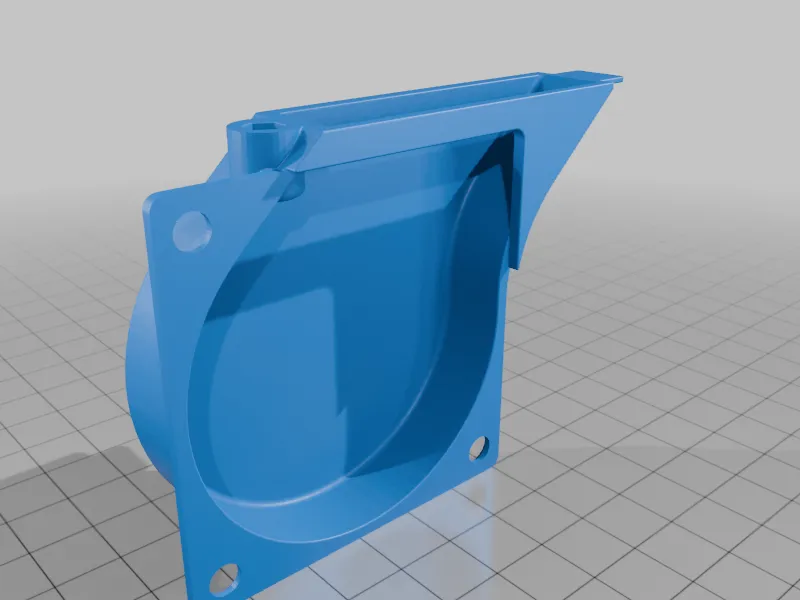
STL model of the air duct
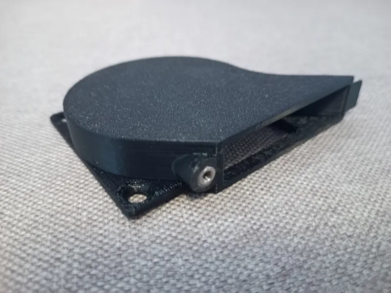
Finished part
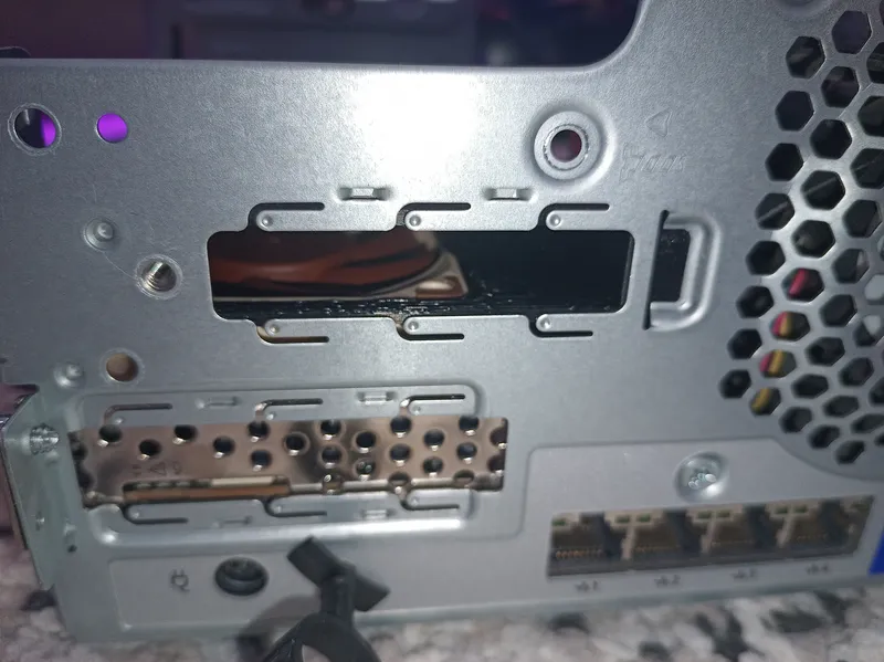
Air intake occurs through the cutout from the HHHL blanking plate
How it looks in the microserver
To make the airflow even more effective, I designed an air duct for my fan in Solidworks. After printing the air duct, I installed a long M3 nut into the hexagonal recess (having previously coated its surface with Poxipol two-component glue). When the glue dried after 10 minutes, I secured the air duct in place of the iLO blanking plate using an M3 screw and fastened the air duct to the fan using connecting screws
Conclusion
I also recommend installing the HPE Proliant Gen 10 Plus microserver in a vertical position (rubber anti-slip pads are included in the kit for this) so that the air intake for the NVMe is at the bottom, and the exhaust of the main cooler fan is at the top.
Discussion (3)
Артём Шагаев
3 Mar 2026
dude this is really cool
Anton Shagaev
3 Mar 2026
Thanks buddy, much appreciated!
Артём Шагаев
3 Mar 2026
круто!!!!
Maker
Anton Shagaev
Tomsk, RU
Anton is the Founding Engineer at Tinkster. He translates industrial reliability into software architecture, ensuring the platform's core is built to last. Anton studied oil and gas engineering in the United States and also holds two honors degrees from Tomsk Polytechnic University.
Related Projects


AI Project Assistant
Tinkster Neural Core
Hi! I am the AI assistant for this project. Ask me any questions about the assembly, code, or components.