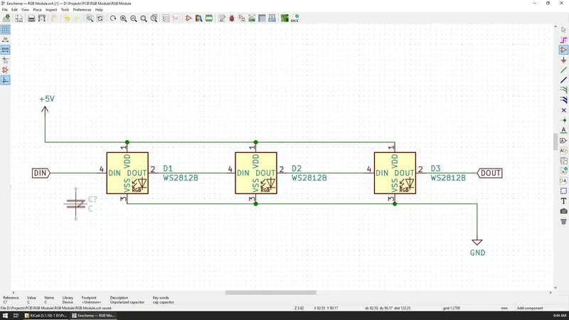
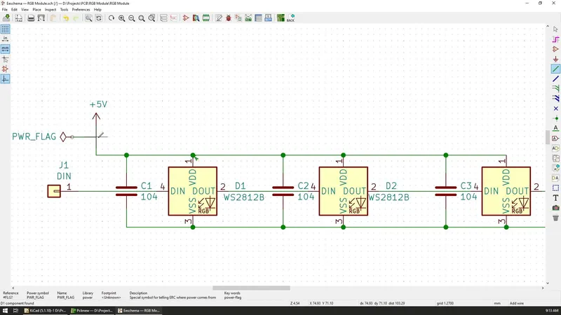
I now had the full schematic ready, so I immediately jumped to convert it to PCB by using the tool in the top toolbar. However, I was reminded by KiCad that I'm missing footprints for some of the components.
A footprint definition specifies the physical appearance of a component in the final PCB. Since a lot of the components can exist in multiple sizes, we must tell KiCad which one to use for each. In my case, the LEDs were already defined but the capacitors were not.
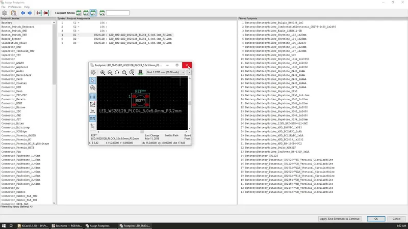
In the "Assign Footprints" window, we get a list of all our components and the current footprint defined for that component.
To view the appearance of the footprint defined for a component we can double click on it and a new window with its preview will appear.
In my case, the current value for the capacitors was empty so I found the Capacitors library on the left and I chose the 1206 size SMD footprint for it. The size that you pick depends on the size of your final board but it also depends on the way that you plan to solder it.
I plan to solder these boards by hand using a regular soldering iron so I chose something that will be big enough for that.
With all of the footprints defined, our next step is to create a so-called netlist for the circuit. Based on Wikipedia, a netlist is a description of the connectivity of an electronic circuit. It defines the different components and the connections between them so the PCB tool can know what to show and what connections we need to make so that it works as defined on the schematic.
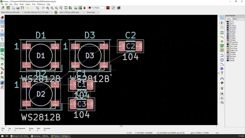
The netlist is easily created and once defined, we need to import it into the PCB editor of KiCad. When the list is imported, all of the components from the schematic are now added to the PCB with small white lines indicating the connection that needs to be made between each of the component pins.
With the components now in the editor, you can start preparing the layout of them but since my PCB will have a special shape, I wanted to first define the shape and work out of that.
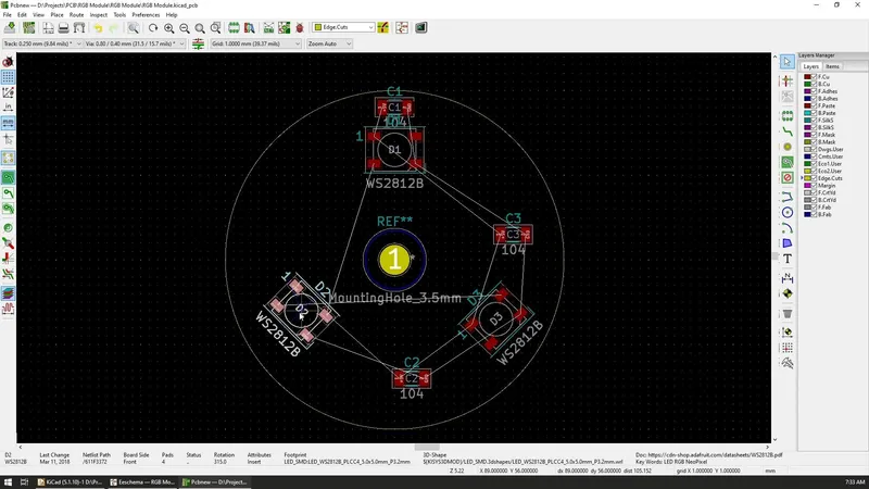
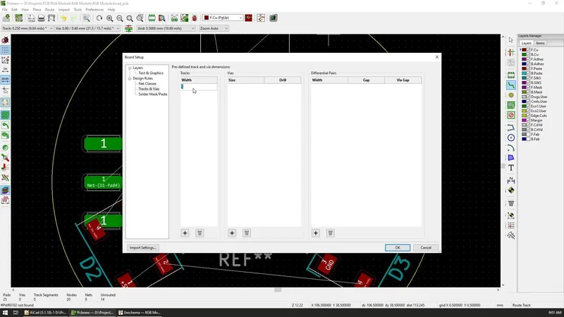
I want the PCB to be circular, so by using the Circle tool and selecting the Edge cut layer on the right, I drew a circle with a diameter of 4cm but I later updated it to 3cm.
To achieve a precise dimension, you can customize the grid spacing by right-clicking with the mouse and selecting new spacing from the grid menu.
With any board, you will probably need to add some mounting holes so it can be secured in place in the final project so, for that, I've added a single 3.5mm hole in the center of the board.
The hole can be added by selecting the Add Footprints option from the toolbar and you can search for mounting holes in the dialog that appears.
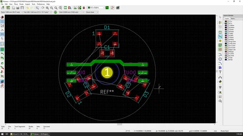
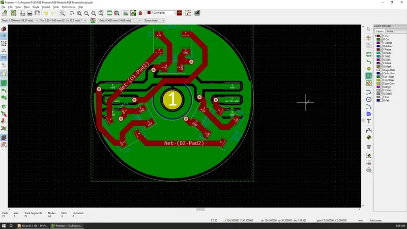
Now, with the outline and the mounting hole defined, our next step is to position the components on the board and we can do this by selecting the component and dragging it around to its new place. We can also rotate any component at any time and create the layout that we want.
Since I have 3 LEDs in my design, I arranged them in a way so that they are equally distributed on the board and 120 degrees apart from each other. The appropriate capacitors are placed right next to the LEDs to provide the voltage smoothing as quickly as possible.
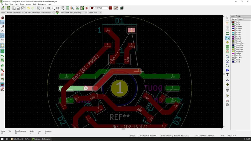
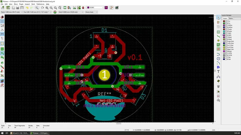
By default, the boards that you will create will have two copper layers, and depending on the components you can choose to add them on either one side or both sides. In my case, all of the components are on the front side, but I will have some solder pads on the bottom side.
To switch between the layers, you can select the layer that you want in the panel on the right and after that, anything that you will place on the board will be added to that layer.
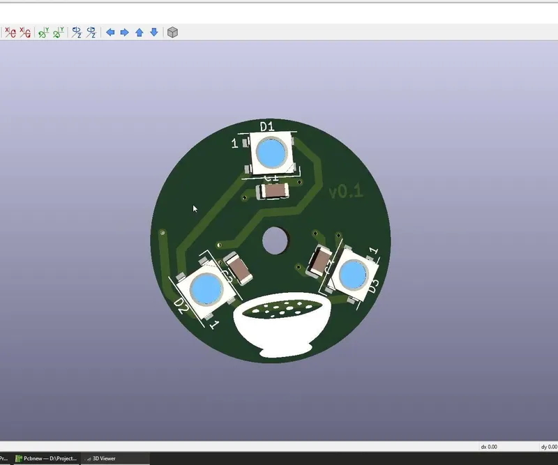
To check your progress and appearance of the board, KiCad offers the ability to preview your board in 3D by pressing on Alt+3 or by selecting the 3D Viewer from the view menu.
The 3d model of the board will contain all of the components and their defined shapes, as well as all of the tracks that are added and any graphics or text as well. I'll be switching to the 3D view occasionally to make sure that I'm on the right track and that I like the output.