advancedAudio & Synth3-Dec-2020
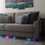
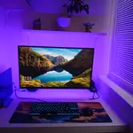
Beautiful color music on addressable RGB strip

Anton Shagaev
Tashkent, UZ
2 days
--
5
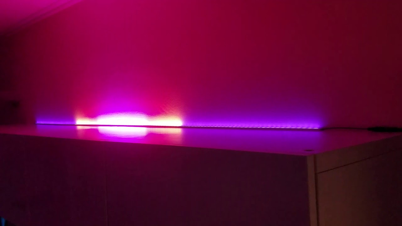
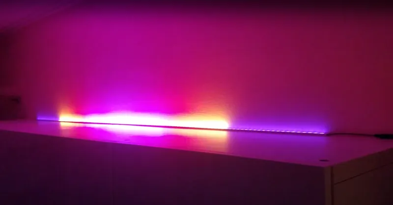
Friends, today we'll talk about how to make a beautiful color organ (light show synchronized to music) using addressable RGB LED strips at home. This technology is based on Arduino Uno or a microcontroller board Atmega328P with open-source firmware. The firmware itself was taken from Alex Gyver but was slightly modified because spontaneous switching of lighting effects occurred periodically. This color organ connects to the right channel of any amplifier or home theater system. Control of the lighting effects is done using an IR remote. The maximum number of LEDs for this firmware version is 410 pieces.
What you'll need
Materials
- 2 m
- 2 m
- 1 pc
- 1 pc
- Enclosure for microcontroller board1 pc
- 1 pc
- Enclosure for power supply1 pc
- Power cord with grounded plug1 pc
- 1 pc
- Any IR remote control1 pc
- Resistor, 100-500 Ohm (any power rating)1 pc
- Resistor, 2.2kOhm, 1W1 pc
- Resistor, 4.7kOhm, 1W1 pc
- Capacitor, 10nF (marking 103)1 pc
- Capacitor, 1000μF, 6.3V1 pc
- Potentiometer, 20kOhm1 pc
- 5.5 x 2.1 mm connector socket, male2 pcs
- 5.5 x 2.1 mm connector socket, for enclosure, female2 pcs
- 3.5 mm connector socket, 3 contacts, male2 pcs
- 3.5 mm connector socket, 3 contacts, for enclosure, female1 pc
- 3.5 mm connector socket, 3 contacts, female1 pc
- Three-core wire, 2mm²3 m
- Audio cable, two-core3 m
- Two-core wire, 2mm²2 m
Steps
1
Reading IR remote control button codes
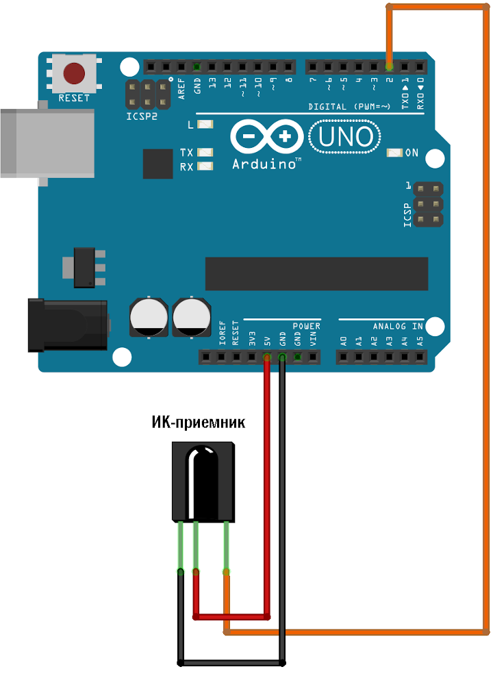
irda1
The drawing is taken from the website alexgyver.ru
Connect the IR receiver to Arduino Uno according to the diagram:
If you are on Windows, install the program Arduino IDE for this operating system. Then download this archive with firmware and libraries. Save the archive on drive C. Unpack the archive. From the folder C:/ColorMusic/libraries copy everything to the folder C:/Documents and Settings/<Your username>/Documents/Arduino/libraries
Next, go to the folder C:/ColorMusic/firmware/IRtest_2.0 and run the file IRtest_2.0.ino. The Arduino IDE will open. Connect the Arduino Uno to the USB port. The Arduino IDE should automatically detect the board model and the data exchange port. Just in case, I recommend checking the board name in Tools -> Board, it should be set to Arduino Genuino/Uno, in Tools -> Port the corresponding data exchange port should be set. If you don't know which port should be set, in Windows you need to go to "Device Manager" and open the menu "USB Controllers".
Next, upload the firmware IRtest_2.0.ino to Arduino Uno. To do this, in Arduino IDE press Sketch -> Upload. Then go Tools -> Serial Monitor. The serial port monitoring window will open.
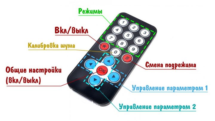
Read the button codes according to the figure:
Copy them into a text file so that it looks like this:
tinkster@almalinux:~#
1#if REMOTE_TYPE == 32#define BUTT_UP 0xE51CA6AD // Up button3#define BUTT_DOWN 0xD22353AD // Down button4#define BUTT_LEFT 0x517068AD // Left button5#define BUTT_RIGHT 0xAC2A56AD // Right button6#define BUTT_OK 0x1B92DDAD // OK button7#define BUTT_1 0x68E456AD // Button with digit 18#define BUTT_2 0xF08A26AD // Button with digit 29#define BUTT_3 0x151CD6AD // Button with digit 310#define BUTT_4 0x18319BAD // Button with digit 411#define BUTT_5 0xF39EEBAD // Button with digit 512#define BUTT_6 0x4AABDFAD // Button with digit 613#define BUTT_7 0xE25410AD // Button with digit 714#define BUTT_8 0x297C76AD // Button with digit 815#define BUTT_9 0x14CE54AD // Button with digit 916#define BUTT_0 0xC089F6AD // Button with digit 017#define BUTT_STAR 0xAF3F1BAD // Power button18#define BUTT_HASH 0x38379AD // Submode switch button19#endif
Save the file.
2
Firmware flashing of color music
Go to the folder C:/ColorMusic/firmware/colorMusic_v2.10 and open the file colorMusic_v2.10.ino
In it, change the following parameters:
tinkster@almalinux:~#
1#define NUM_LEDS 120 // Total number of LEDs on the addressable strip.2#define CURRENT_LIMIT 10000 // Current limit 10A. Will also automatically control LED brightness when the current threshold is reached.
After the inscription // —— CUSTOM REMOTE BUTTONS —— delete from #if REMOTE_TYPE == 3 to #endif. Then insert the block with remote buttons that we saved earlier.
Save the file and upload the sketch to Arduino Uno via Sketch -> Upload.
3
Assembling a color music control unit
Assembling a color music control unit
Assembling a color music control unit
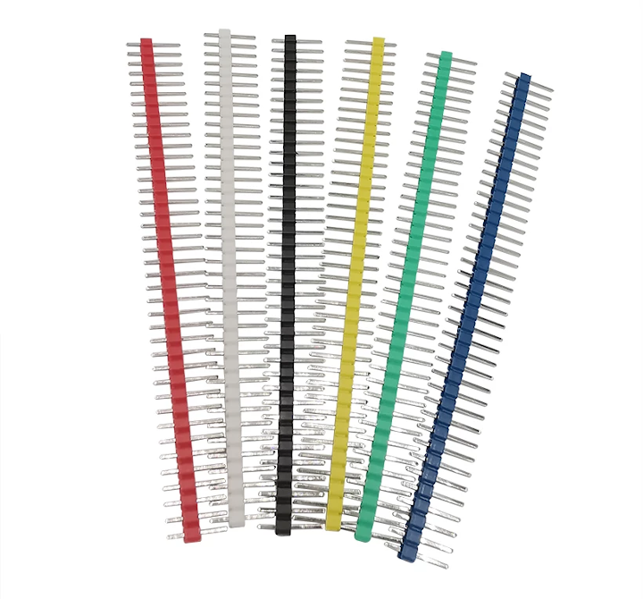
arduino_male_pin_connectors
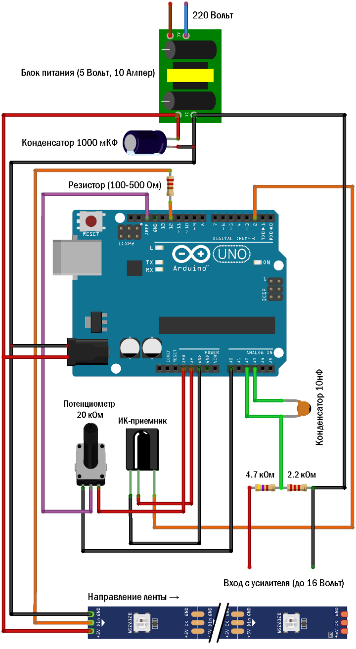
color_music_schematic1
We assemble the color music control unit according to the diagram:
I recommend taking good flux (I used TAGS) and solder. For soldering to the Arduino, you need to take these pin headers, insert them into the Arduino, and then solder to them.
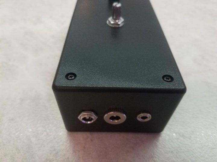
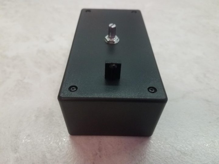
The case design will be different for everyone, but in the end, mine turned out like this:
It's better to drill the holes for the connector sockets on a drill press so the drill bit doesn't wander off course. For the 3.5mm connector socket, I had to thin out the area of the box wall around its hole from the inside so I could screw on the mating nut from the outside. For this, I used a Dremel multi-tool with an abrasive attachment.
We also solder all the sockets to the wires and then test them with a multimeter to immediately rule out soldering errors.
4
Laying the LED strip in the profile
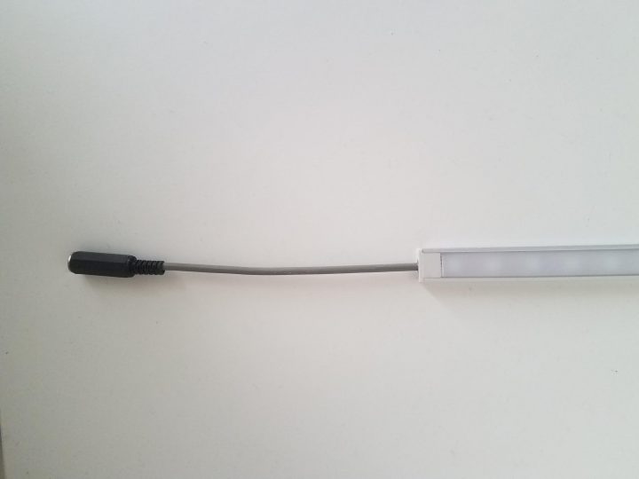
Laying the LED strip in the profile
Carefully remove the diffuser from the LED strip profile, peel off the protective layer of the double-sided tape, and glue the strip into the profile. Pay attention to the direction of the LED strip, which will be indicated by small arrows on the strip itself. At the very beginning of the direction, solder the three contacts of the three-core cable and carefully route the cable out of the profile, having soldered it to the 3.5mm jack socket accordingly. After completing this work, carefully place the profile diffuser back in position.
After all manipulations, connect the two-core cable of the color music control unit to the right channel of the amplifier and plug the unit into the power outlet.
5
Reference voltage adjustment
The reference voltage adjustment potentiometer is adjusted by "trial and error" until it works. Adjustment is needed when changing the audio source or altering its potential volume.
If during operation in VU meter mode (the first two modes) the scale is constantly lit—the reference voltage is too low, and the Arduino is receiving too high a signal. If it does not light up—the reference voltage is too high, and the system cannot detect volume changes with sufficient accuracy for operation.
6
Noise calibration
Turn on the music and set the volume to medium for everyday listening. Then pause the music. Hold down button 0 on the IR remote for 1 second. During this time, the LED on the Arduino board will light up and then turn off after approximately 1.5 seconds. The noise values will be recorded in memory and will automatically load upon subsequent startup.
Unpause the music and enjoy the color music effects!
Conclusion
Discussion (0)
No comments yet. Be the first!
Maker
Anton Shagaev
Tashkent, UZ
Anton is the Founding Engineer at Tinkster. He translates industrial reliability into software architecture, ensuring the platform's core is built to last. Anton studied oil and gas engineering in the United States and also holds two honors degrees from Tomsk Polytechnic University.
Related Projects
AI Project Assistant
Tinkster Neural Core
Hi! I am the AI assistant for this project. Ask me any questions about the assembly, code, or components.