advancedSmart Home & IoT11-Mar-2025
Automatic warm water discharge system for reverse osmosis filters

Anton Shagaev
Tashkent, UZ
7 days
--
11
Friends, in one of my apartments, a problem with the cold water temperature recently arose, and it has not been resolved since then. Possibly, in the central water supply system of my building, hot water is being mixed somewhere into the cold water pipe, and because of this, water with a temperature of 36–39 degrees is coming from the cold water tap.
Such an elevated temperature from the cold water pipe negatively affects the operation of my reverse osmosis (RO) water purification system, as well as the operation of my water ionization device, since it is connected after the three RO pre-filters. According to , water up to 38 degrees can be supplied to the RO system, and up to 30 degrees Celsius to the water ionization device. In practice, it is recommended to use water with a temperature of 4–30 °C for optimal RO system operation. Also, water temperature of 25-35 °C can promote active bacterial growth in the storage tank of the reverse osmosis system, but this is solved by installing a UV filter.
After draining such water from the tap for 5 minutes, the water becomes about 27 degrees Celsius. It was decided to make an automatic warm water discharge system based on ESP32 and Home Assistant.
What you'll need
Materials
- Control unit box1 pc
- 1 pc
- 1 pc
- 1 pc
- 1 pc
- 1 pc
- 1 pc
- 4 pcs
- 1 pc
- 1 pc
- 1 pc
- 1 pc
- Heat shrink for steel pipe d18 mm — 50 mm1 pc
- Thermal insulation for steel pipe inner diam. 16 mm — 50 mm1 pc
- 2 pcs
- 6 pcs
- 2 pcs
- 3 pcs
- 8 pcs
- 1 pc
- 4 pcs
- Resistor 4.7 kOhm, 1/4 W1 pc
- 3 pcs
- Diode 1N40013 pcs
- Transistor 2N39043 pcs
- Resistor 1 kOhm, 1/4 W3 pcs
- 2 pcs
- 1 pc
- Resistor 240 Ohm, 1/4 W3 pcs
- 1 pc
- 2 pcs
- Resistor 2.4 kOhm, 1/4 W3 pcs
Steps
1
We manufacture a temperature sensor
Thermal sensors
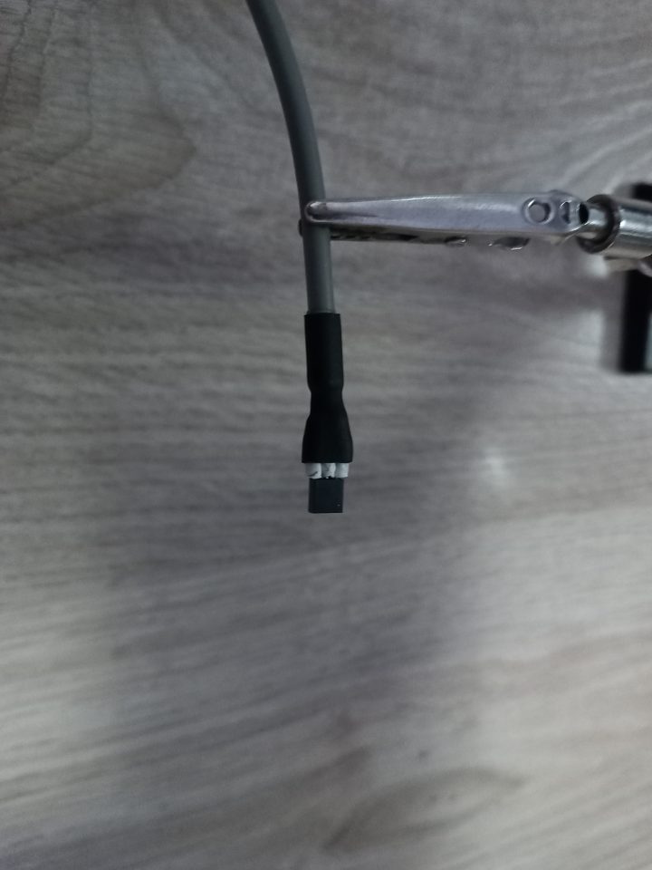
DS18B20 temperature sensor
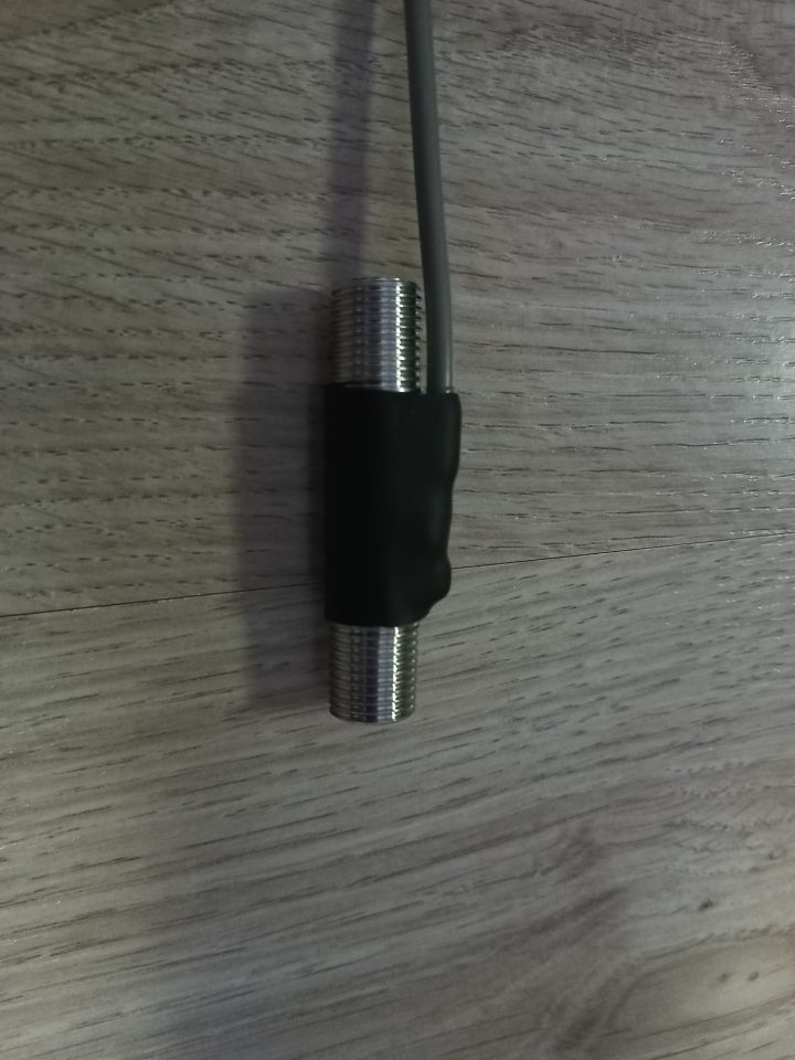
Temperature sensor attached to 1/4 BSP pipe using heat shrink tubing
Take the temperature sensor and solder a three-core signal wire to it. Do not forget about contact labeling to know where Data, Ground, and VDC are. Secure the sensor to the metal pipe using heat shrink tubing. Connect the pipe itself to two 1/4BSP – 1/4 Hose fittings. Then place the pipe in thermal insulation.
And here are the ready temperature sensors (I made an additional temperature sensor for another project):
2
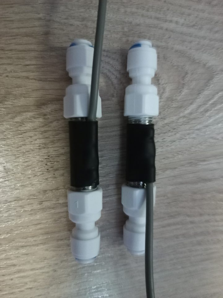
Assembling the manifold block
Assembling the manifold block
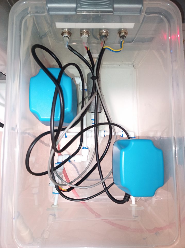
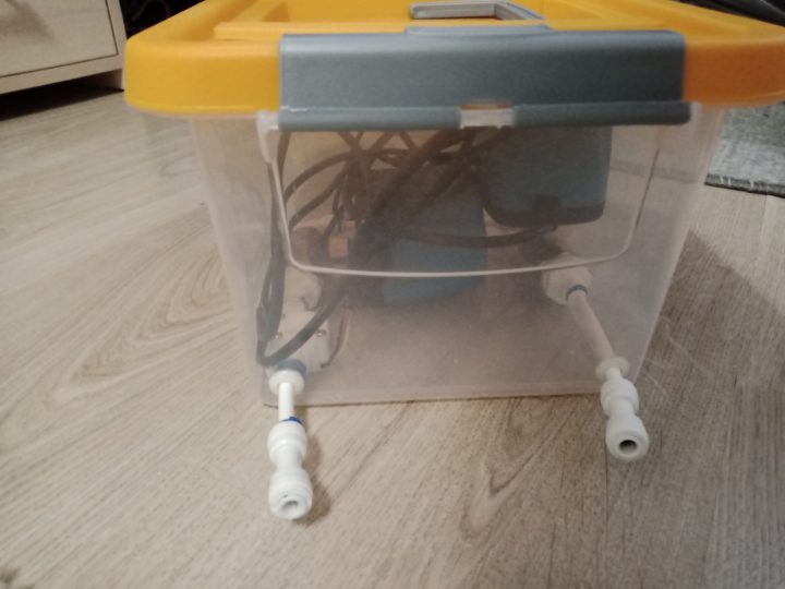
Manifold block
Each electric ball valve will have its own enclosure, so the number of connecting fittings will vary. In my case, I purchased a storage container with a lid, drilled three holes in it for 1/4" tubing, as well as four holes for the GX12 connector plug on the housing. I placed a temperature sensor, two electric ball valves, a flow meter inside this enclosure, and connected everything with reverse osmosis system fittings. I soldered the wires from the electric ball valves, temperature sensor, and flow meter to the corresponding outputs of the GX12 connector plugs.
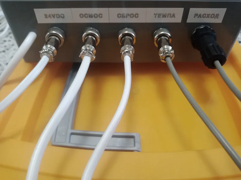
3
Control unit soldering
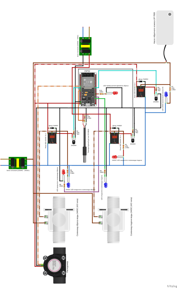
Control unit soldering
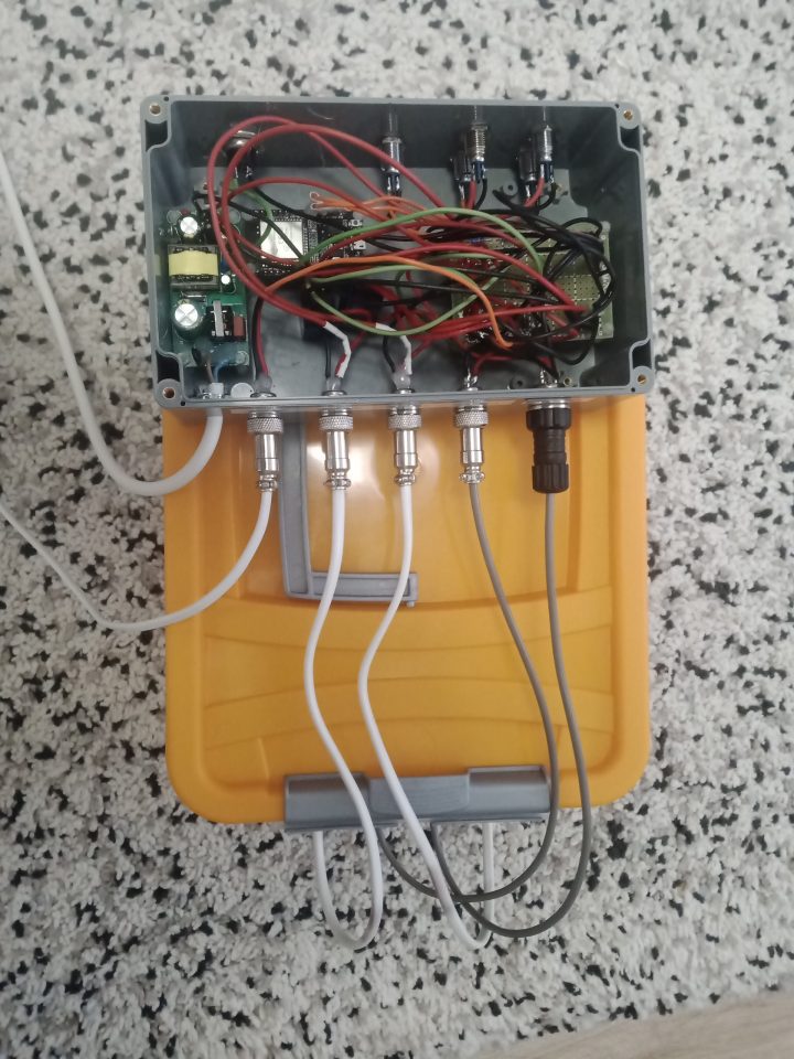
Control unit

Back side of the control unit
Here everything is also extremely simple. Drill the corresponding holes in the box for the GX12, LEDs, and 220VAC power cable. Assemble the components according to the diagram.
4
Upload the program to ESP32
Connect the ESP32 to the laptop, open Arduino IDE and upload the following sketch:
tinkster@almalinux:~#
1#include <Arduino.h>2#include <WiFi.h>3#include <WiFiClient.h>4#include <OneWire.h>5#include <DallasTemperature.h>6#include <mqtt_client.h>7#include "esp_heap_caps.h"89#if __has_include(<esp_arduino_version.h>)10#include <esp_arduino_version.h>11#endif1213// ================== CONFIGURATION ==================14// WiFi parameters15#define WIFI_SSID "HomeNetwork"16#define WIFI_PASSWORD "SecurePass2024"17IPAddress staticIP(192, 168, 1, 100);18IPAddress gateway(192, 168, 1, 1);19IPAddress subnet(255, 255, 255, 0);2021// MQTT broker parameters22#define MQTT_HOST "192.168.1.50"23#define MQTT_PORT 188324#define MQTT_USER "device_user"25#define MQTT_PASSWORD "mqtt_secure_pass"2627// MQTT topics28#define MQTT_TOPIC_WATER_TEMPERATURE "homeassistant/ro_system/water_temperature"29#define MQTT_TOPIC_RO_SOLENOID "homeassistant/ro_system/ro_solenoid"30#define MQTT_TOPIC_DRAINAGE_SOLENOID "homeassistant/ro_system/drainage_solenoid"31#define MQTT_TOPIC_RO_PUMP "homeassistant/ro_system/ro_pump"32#define MQTT_TOPIC_DUMPED_WATER_INTERVAL_VOLUME "homeassistant/ro_system/dumped_water_interval_volume"33#define MQTT_TOPIC_SYSTEM_STATE "homeassistant/ro_system/system_state"34#define MQTT_TOPIC_DUMP_TIME "homeassistant/ro_system/dump_time"35#define MQTT_TOPIC_DUMP_TEMP_THRESHOLD "homeassistant/ro_system/dump_temp_threshold"3637// ================== GPIO ==================38#define RO_SOLENOID_PIN 26 // Supply valve39#define DRAINAGE_SOLENOID_PIN 25 // Drain valve40#define ONE_WIRE_BUS 27 // DS18B20 temperature sensor41#define FLOW_METER_PIN 33 // Flow meter42#define RO_BLUE_LED 15 // Blue LED43#define DRAINAGE_RED_LED 2 // Red LED44#define DUMP_TIMEOUT_RED_LED 4 // Error LED45#define RO_PUMP_PIN 18 // Booster pump4647// ================== STATE ENUMS ==================48// Pump command state (debounce)49enum PumpCommandState {50PUMP_CMD_IDLE=0,51PUMP_CMD_PENDING=1,52PUMP_CMD_CONFIRMED=253};5455// System state56enum SystemState {57STATE_NORMAL=0, // Normal operation58STATE_DUMP_IN_PROGRESS=1, // Warm water dump in progress59STATE_PUMP_DELAYED_START=2,// Delay before pump restart60STATE_DUMP_TIMEOUT=3 // Error: dump timeout exceeded61};6263// ================== SENSORS AND MQTT ==================64OneWire oneWire(ONE_WIRE_BUS);65DallasTemperature sensors(&oneWire);6667static esp_mqtt_client_handle_t mqtt_client = NULL;68static char mqtt_publish_buf[128];69static char mqtt_topic_buf[128];70static char mqtt_data_buf[64];7172// ================== SYSTEM STATE ==================73SystemState system_state = STATE_NORMAL;74PumpCommandState pump_cmd_state = PUMP_CMD_IDLE;7576bool ro_solenoid_open = true;77bool drainage_solenoid_open = false;78bool ro_pump_enabled = true;79bool mqtt_control_allowed = true;8081// ================== PARAMETERS ==================82float water_temperature = 0.0;83long dump_time_ms = 600000; // Dump time (ms)84float dump_temp_threshold = 29.0; // Temperature threshold for dump (°C)85float dump_temp_hysteresis = 2.0; // Hysteresis (°C)86const long pump_restart_delay = 15000; // Pump restart delay (ms)8788bool pump_cmd_pending_value = false;89unsigned long pump_cmd_timestamp = 0;9091// ================== TIMERS ==================92unsigned long last_sensor_update = 0;93unsigned long last_status_update = 0;94unsigned long dump_start_time = 0;95unsigned long pump_restart_time = 0;96unsigned long last_heap_check = 0;9798const long sensor_interval = 5000;99const long STATUS_UPDATE_INTERVAL = 5000;100const long led_update_interval = 100;101102// ================== FLOW METER ==================103portMUX_TYPE mux = portMUX_INITIALIZER_UNLOCKED;104volatile uint32_t pulseCount = 0;105volatile bool wifiReconnectNeeded = false;106volatile bool mqttReconnectNeeded = false;107const float FLOW_COEFFICIENT = 0.1622168797; // Pulses -> liters108109// ================== STATUS STRINGS ==================110const char* solenoid_open_name = "Open";111const char* solenoid_closed_name = "Closed";112const char* status_normal = "Water supply to reverse osmosis";113const char* status_dump = "Warm water dump";114const char* status_dump_timeout = "Dump timeout exceeded";115const char* deviceName = "ESP32RO";116117// ================== LOGGING AND MQTT ==================118119// Logging with timestamp and category120void logInfoF(const char* category, const char* format, ...) {121unsigned long timestamp = millis();122char buf[128];123va_list args;124va_start(args, format);125vsnprintf(buf, sizeof(buf), format, args);126va_end(args);127Serial.printf("[%lu] [%s] %sn", timestamp, category, buf);128}129130// Publish to MQTT (QoS=1, no retain)131void publishMqtt(const char* topic, const char* payload) {132if (mqtt_client) {133esp_mqtt_client_publish(mqtt_client, topic, payload, 0, 1, 0);134}135}136137// ================== HELPER PUBLISH FUNCTIONS ==================138139void publishRoSolenoidStatus() {140publishMqtt(MQTT_TOPIC_RO_SOLENOID, ro_solenoid_open ? solenoid_open_name : solenoid_closed_name);141}142143void publishDrainageSolenoidStatus() {144publishMqtt(MQTT_TOPIC_DRAINAGE_SOLENOID, drainage_solenoid_open ? solenoid_open_name : solenoid_closed_name);145}146147void publishPumpStatus() {148publishMqtt(MQTT_TOPIC_RO_PUMP, ro_pump_enabled ? "1" : "0");149}150151void publishSystemState() {152const char* state_str;153switch (system_state) {154case STATE_DUMP_IN_PROGRESS:155state_str = status_dump;156break;157case STATE_DUMP_TIMEOUT:158state_str = status_dump_timeout;159break;160case STATE_PUMP_DELAYED_START:161case STATE_NORMAL:162default:163state_str = status_normal;164break;165}166publishMqtt(MQTT_TOPIC_SYSTEM_STATE, state_str);167}168169// ================== COMPONENT CONTROL ==================170171// Control supply valve (LOW opens, HIGH closes)172void setRoSolenoid(bool open) {173if (ro_solenoid_open != open) {174ro_solenoid_open = open;175digitalWrite(RO_SOLENOID_PIN, open ? LOW : HIGH);176logInfoF("RO_SOL", "Changed to: %s", open ? "OPEN" : "CLOSED");177publishRoSolenoidStatus();178}179}180181// Control drain valve (HIGH opens, LOW closes)182void setDrainageSolenoid(bool open) {183if (drainage_solenoid_open != open) {184drainage_solenoid_open = open;185digitalWrite(DRAINAGE_SOLENOID_PIN, open ? HIGH : LOW);186logInfoF("DRAIN_SOL", "Changed to: %s", open ? "OPEN" : "CLOSED");187publishDrainageSolenoidStatus();188}189}190191// Control pump (LOW turns on, HIGH turns off)192// Blocks turning on during dump and cooling193void setPumpEnabled(bool enabled) {194if (enabled && (system_state == STATE_DUMP_IN_PROGRESS || system_state == STATE_PUMP_DELAYED_START)) {195logInfoF("PUMP", "Block: System State %d", system_state);196return;197}198199if (ro_pump_enabled != enabled) {200ro_pump_enabled = enabled;201digitalWrite(RO_PUMP_PIN, enabled ? LOW : HIGH);202logInfoF("PUMP", "Changed to: %s", enabled ? "ON" : "OFF");203publishPumpStatus();204}205}206207// ================== SYSTEM LOGIC ==================208209// Main system control logic:210// 1. Overheat detection -> start dump211// 2. Cooling detection -> delay before restart212// 3. Dump timeout -> error213// 4. Delay completion -> return to normal214void handleSystemLogic() {215unsigned long now = millis();216217// STAGE 1: OVERHEAT - START DUMP218if (system_state == STATE_NORMAL && water_temperature > dump_temp_threshold) {219logInfoF("SYSTEM", "Temp too high (%.1f), starting DUMP", water_temperature);220system_state = STATE_DUMP_IN_PROGRESS;221dump_start_time = now;222223setRoSolenoid(false); // Close supply224setDrainageSolenoid(true); // Open drain225setPumpEnabled(false); // Turn off pump226mqtt_control_allowed = false;227228publishSystemState();229}230231// STAGE 2: COOLING - DELAY BEFORE RESTART232if (system_state == STATE_DUMP_IN_PROGRESS && water_temperature < (dump_temp_threshold - dump_temp_hysteresis)) {233logInfoF("SYSTEM", "Temp normal (%.1f), waiting...", water_temperature);234system_state = STATE_PUMP_DELAYED_START;235pump_restart_time = now;236237setRoSolenoid(true); // Open supply238setDrainageSolenoid(false); // Close drain239mqtt_control_allowed = false;240241publishSystemState();242}243244// STAGE 3: DUMP TIMEOUT - ERROR245if (system_state == STATE_DUMP_IN_PROGRESS && (now - dump_start_time) >= dump_time_ms) {246logInfoF("SYSTEM", "DUMP TIMEOUT! Error!");247system_state = STATE_DUMP_TIMEOUT;248249setRoSolenoid(false);250setDrainageSolenoid(false);251setPumpEnabled(false);252mqtt_control_allowed = false;253254publishSystemState();255}256257// STAGE 4: DELAY COMPLETED - RETURN TO NORMAL258if (system_state == STATE_PUMP_DELAYED_START && (now - pump_restart_time) >= pump_restart_delay) {259logInfoF("SYSTEM", "Back to Normal.");260system_state = STATE_NORMAL;261262setPumpEnabled(true);263mqtt_control_allowed = true;264265publishSystemState();266}267}268269// Process pump control commands with debounce (300ms)270void handlePumpCommand() {271unsigned long now = millis();272switch(pump_cmd_state) {273case PUMP_CMD_IDLE:274break;275276case PUMP_CMD_PENDING:277// Wait for debounce278if (now - pump_cmd_timestamp >= 300)279pump_cmd_state = PUMP_CMD_CONFIRMED;280break;281282case PUMP_CMD_CONFIRMED:283// Execute command if state allows284if (mqtt_control_allowed && system_state != STATE_DUMP_TIMEOUT) {285setPumpEnabled(pump_cmd_pending_value);286}287pump_cmd_state = PUMP_CMD_IDLE;288break;289}290}291292// ================== SENSORS AND HEARTBEAT ==================293294// Flow meter interrupt295void IRAM_ATTR pulseCounter() {296portENTER_CRITICAL_ISR(&mux);297pulseCount++;298portEXIT_CRITICAL_ISR(&mux);299}300301// Sensor polling (temperature and flow)302void handleSensorUpdate() {303if (millis() - last_sensor_update < sensor_interval) return;304last_sensor_update = millis();305306sensors.requestTemperatures();307float t = sensors.getTempCByIndex(0);308if (t > -50 && t < 100) water_temperature = t;309310// Read flow meter311uint32_t pulses;312portENTER_CRITICAL(&mux);313pulses = pulseCount;314pulseCount = 0;315portEXIT_CRITICAL(&mux);316317float intervalVolume = pulses * FLOW_COEFFICIENT;318319snprintf(mqtt_publish_buf, sizeof(mqtt_publish_buf), "%.2f", water_temperature);320publishMqtt(MQTT_TOPIC_WATER_TEMPERATURE, mqtt_publish_buf);321322snprintf(mqtt_publish_buf, sizeof(mqtt_publish_buf), "%.2f", intervalVolume);323publishMqtt(MQTT_TOPIC_DUMPED_WATER_INTERVAL_VOLUME, mqtt_publish_buf);324}325326// Periodic status update to Home Assistant327void publishStatusHeartbeat() {328if (millis() - last_status_update < STATUS_UPDATE_INTERVAL) return;329last_status_update = millis();330331if (mqtt_client) {332publishRoSolenoidStatus();333publishDrainageSolenoidStatus();334publishPumpStatus();335publishSystemState();336337snprintf(mqtt_publish_buf, sizeof(mqtt_publish_buf), "%ld", dump_time_ms / 60000);338publishMqtt(MQTT_TOPIC_DUMP_TIME, mqtt_publish_buf);339340snprintf(mqtt_publish_buf, sizeof(mqtt_publish_buf), "%.1f", dump_temp_threshold);341publishMqtt(MQTT_TOPIC_DUMP_TEMP_THRESHOLD, mqtt_publish_buf);342}343}344345// ================== MQTT HANDLER ==================346347// MQTT event handler348static void mqtt_event_handler(void* handler_args, esp_event_base_t base, int32_t event_id, void* event_data) {349esp_mqtt_event_handle_t event = (esp_mqtt_event_handle_t) event_data;350switch((esp_mqtt_event_id_t)event_id) {351case MQTT_EVENT_CONNECTED:352logInfoF("MQTT","Connected");353354// Subscribe to control topics355esp_mqtt_client_subscribe(mqtt_client, MQTT_TOPIC_RO_PUMP, 0);356esp_mqtt_client_subscribe(mqtt_client, MQTT_TOPIC_DUMP_TIME, 0);357esp_mqtt_client_subscribe(mqtt_client, MQTT_TOPIC_DUMP_TEMP_THRESHOLD, 0);358359// Send full status on connection360publishRoSolenoidStatus();361publishDrainageSolenoidStatus();362publishPumpStatus();363publishSystemState();364365snprintf(mqtt_publish_buf, sizeof(mqtt_publish_buf), "%.2f", water_temperature);366publishMqtt(MQTT_TOPIC_WATER_TEMPERATURE, mqtt_publish_buf);367break;368369case MQTT_EVENT_DATA: {370if (event->topic_len >= sizeof(mqtt_topic_buf) || event->data_len >= sizeof(mqtt_data_buf)) break;371372memcpy(mqtt_topic_buf, event->topic, event->topic_len);373mqtt_topic_buf[event->topic_len] = 0;374memcpy(mqtt_data_buf, event->data, event->data_len);375mqtt_data_buf[event->data_len] = 0;376377// Pump on/off command378if (strncmp(mqtt_topic_buf, MQTT_TOPIC_RO_PUMP, event->topic_len) == 0) {379bool new_state = (atoi(mqtt_data_buf) != 0);380pump_cmd_pending_value = new_state;381pump_cmd_state = PUMP_CMD_PENDING;382pump_cmd_timestamp = millis();383}384// Change dump temperature threshold385else if (strncmp(mqtt_topic_buf, MQTT_TOPIC_DUMP_TEMP_THRESHOLD, event->topic_len) == 0) {386dump_temp_threshold = atof(mqtt_data_buf);387logInfoF("CONF", "New Temp: %.1f", dump_temp_threshold);388}389// Change dump time (in minutes)390else if (strncmp(mqtt_topic_buf, MQTT_TOPIC_DUMP_TIME, event->topic_len) == 0) {391dump_time_ms = atol(mqtt_data_buf) * 60000;392logInfoF("CONF", "New Time: %ld ms", dump_time_ms);393}394} break;395default:396break;397}398}399400// Initialize MQTT client401void mqtt_setup() {402if (mqtt_client) {403esp_mqtt_client_stop(mqtt_client);404esp_mqtt_client_destroy(mqtt_client);405mqtt_client = NULL;406}407408esp_mqtt_client_config_t mqtt_cfg = {};409410#if defined(ESP_ARDUINO_VERSION_MAJOR) && ESP_ARDUINO_VERSION_MAJOR >= 3411mqtt_cfg.broker.address.hostname = MQTT_HOST;412mqtt_cfg.broker.address.port = MQTT_PORT;413mqtt_cfg.credentials.username = MQTT_USER;414mqtt_cfg.credentials.authentication.password = MQTT_PASSWORD;415#else416mqtt_cfg.host = MQTT_HOST;417mqtt_cfg.port = MQTT_PORT;418mqtt_cfg.username = MQTT_USER;419mqtt_cfg.password = MQTT_PASSWORD;420#endif421422mqtt_client = esp_mqtt_client_init(&mqtt_cfg);423if (mqtt_client) {424esp_mqtt_client_register_event(mqtt_client, M
All specified libraries in the sketch must be installed in advance. Note that in the formulaintervalVolume = pulseCount * 0.1622168797, the coefficient 0.1622168797 means the number of milliliters per each revolution of the flowmeter turbine.
5
Setting up Home Assistant
Setting up Home Assistant
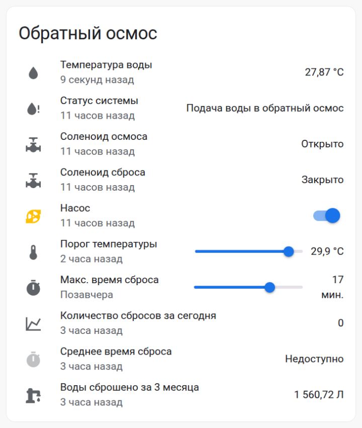
The connection between ESP32 and Home Assistant (HA) is established via an MQTT broker. In HA, create the following card:
tinkster@almalinux:~#
1type: entities2entities:3- entity: sensor.water_temperature4secondary_info: last-changed5name: Water Temperature6icon: mdi:water7- entity: sensor.ro_system_state8secondary_info: last-changed9name: System Status10icon: mdi:water-alert11- entity: sensor.ro_solenoid_status12secondary_info: last-changed13name: RO Solenoid14icon: mdi:pipe-valve15- entity: sensor.drainage_solenoid_status16secondary_info: last-changed17name: Drain Solenoid18icon: mdi:pipe-valve19- entity: switch.ro_pump20secondary_info: last-changed21name: Pump22icon: mdi:pump23- entity: input_number.dump_temp_threshold24secondary_info: last-changed25name: Temperature Threshold26- entity: input_number.dump_time27name: Max Dump Time28secondary_info: last-changed29- entity: sensor.water_dump_counts_for_today30secondary_info: last-changed31name: Dump Count Today32- entity: sensor.average_dump_time_today33secondary_info: last-changed34name: Average Dump Time35icon: mdi:timer36show_header_toggle: false37title: Reverse Osmosis38state_color: true
В configuration.yaml add the following lines:
tinkster@almalinux:~#
1sensor:2- platform: template3sensors:4average_dump_time_today:5unit_of_measurement: 'мин.'6friendly_name: "Average dump time today"7value_template: "{{ ((states('sensor.water_dumps_total_time_for_today')|float / states('sensor.water_dump_counts_for_today')|float) * 60)|round(1) }}"8- platform: history_stats9name: Water dump counts for today10entity_id: sensor.ro_system_state11state: "Warm water dump" # Changed from "Сброс тёплой воды"12type: count13start: "{{ now().replace(hour=0, minute=0, second=0) }}"14end: "{{ now() }}"15- platform: history_stats16name: Water dumps total time for today17entity_id: sensor.ro_system_state18state: "Warm water dump" # Changed from "Сброс тёплой воды"19type: time20start: "{{ now().replace(hour=0, minute=0, second=0) }}"21end: "{{ now() }}"22input_number:23dump_time:24name: Dump time25mode: slider26unit_of_measurement: "мин."27icon: mdi:timer28min: 1029max: 2030step: 131dump_temp_threshold:32name: Dump temp threshold33mode: slider34unit_of_measurement: "°C"35icon: mdi:thermometer36min: 2237max: 3138step: 0.1
В automations.yaml add the following:
tinkster@almalinux:~#
1- id: 'XXXXXXXXXXXX1'2alias: Send maximum water dump time value via MQTT3description: ''4trigger:5- platform: state6entity_id: input_number.dump_time7condition: []8action:9- data:10topic: homeassistant/ro_system/dump_time11payload: '{{ states(''input_number.dump_time'') }}'12retain: true13action: mqtt.publish14mode: single15- id: 'XXXXXXXXXXXX2'16alias: Send water temperature threshold value via MQTT17description: ''18trigger:19- platform: state20entity_id: input_number.dump_temp_threshold21condition: []22action:23- data:24topic: homeassistant/ro_system/dump_temp_threshold25payload: '{{ states(''input_number.dump_temp_threshold'') }}'26retain: true27action: mqtt.publish28mode: single29- id: 'XXXXXXXXXXXX3'30alias: Set maximum water dump time value from MQTT on the slider31description: ''32trigger:33- platform: mqtt34topic: homeassistant/ro_system/dump_time35condition: []36action:37service: input_number.set_value38data_template:39entity_id: input_number.dump_time40value: '{{ trigger.payload }}'41mode: single42- id: 'XXXXXXXXXXXX4'43alias: Set water temperature threshold value from MQTT on the slider44description: ''45trigger:46- platform: mqtt47topic: homeassistant/ro_system/dump_temp_threshold48condition: []49action:50- service: input_number.set_value51data_template:52entity_id: input_number.dump_temp_threshold53value: '{{ trigger.payload }}'54mode: single
6
Connecting the reverse osmosis system
Connect the water supply tube from the cold water to the inlet of the manifold block. Connect the outlet from the normally open (NO) electric ball valve to the inlet of the reverse osmosis system, and connect the outlet from the normally closed (NC) electric ball valve to the drain tube via a T-fitting. Then connect the manifold block to the control unit and test the system. In my case, the reverse osmosis system includes a booster pump, and it is also connected to the control unit. If the temperature sensor detects that the incoming water temperature exceeds the threshold, the water supply to the reverse osmosis system will close, and simultaneously, water will begin to discharge to the drain. The control unit will also turn off the reverse osmosis booster pump. After the water temperature drops, the reverse process will occur, and the booster pump will turn on 15 seconds after the electric ball valves begin to close. If for some reason the temperature does not drop below 2 degrees from the threshold temperature set on the slider and within the set drain time in Home Assistant, the drain will automatically close, and a red error LED on the control unit housing will light up.
Conclusion
Profit :)
Discussion (0)
No comments yet. Be the first!
Maker
Anton Shagaev
Tashkent, UZ
Anton is the Founding Engineer at Tinkster. He translates industrial reliability into software architecture, ensuring the platform's core is built to last. Anton studied oil and gas engineering in the United States and also holds two honors degrees from Tomsk Polytechnic University.
Related Projects

AI Project Assistant
Tinkster Neural Core
Hi! I am the AI assistant for this project. Ask me any questions about the assembly, code, or components.